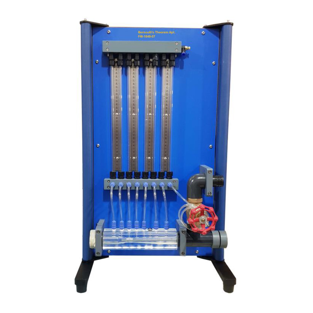
Bernoulli’s Theorem Apparatus consists of a classical Venturi made of clear acrylic. A series of wall tappings allow measurement of the static pressure distribution along the converging duct, while a total head tube is provided to traverse along the center line of the test section. These tappings are connected to a manometer bank incorporating a manifold with an air bleed valve. Pressurization of the manometers is facilitated by a hand pump. This unit has been designed to be used with a Hydraulics Bench for students to study the characteristics of flow through both converging and diverging sections. During the experiment, water is fed through a hose connector and students may control the flow rate of the water by adjusting a flow regulator valve at the outlet of the test section. The venturi can be demonstrated as a means of flow measurement and the discharge coefficient can be determined. This test section can be used to demonstrate those circumstances to which Bernoulli’s Theorem may be applied as well as in other circumstances where the theorem is not sufficient to describe the fluid behavior. The unit is mounted on a base board which is to be placed on top of the Hydraulic Bench. This baseboard has four adjustable feet to level the apparatus. The main test section is an accurately machined acrylic venturi of varying circular cross sections. It is provided with a number of side-hole pressure tappings, which are connected to the manometer tubes on the rig. These tappings allow the measurement of static pressure head simultaneously at each of the 8 sections. The test section incorporates two unions, one at either end, to facilitate reversal for convergent or divergent testing. A hypodermic tube, the total pressure head probe, is provided which may be positioned to read the total pressure head at any section of the duct. This total pressure head probe may be moved after slacking the gland nut; this nut should be re-tightened by hand after adjustment. All eight pressure tapings are connected to a bank of pressurized manometer tubes. Pressurization of the manometers is facilitated by connecting any hand pump to the inlet valve on the manometer manifold. The unit is connected to the hydraulic bench using flexible hoses. The hoses and the connections are equipped with rapid-action couplings. A flow control valve is incorporated downstream of the test section. Flow rate and pressure in the apparatus may be varied independently by adjustment of the flow control valve and the bench supply control valve.
Experiments
- Energy conversion in divergent/convergent pipe flow.
- Determining the flow coefficient.
- Demonstrate Bernoulli’s theorem.
Specifications
The unit consists of the following:
a) Venturi
The venturi meter is made of transparent
acrylic with the following specifications:
Throat diameter: 16 mm
Upstream Diameter: 26 mm
Designed Flow Rate: 20 LPM
b) Manometer
There are eight manometer tubes; each
length 320 mm, for static pressure and total head measuring along the venturi meter. The manometer
tubes are connected to an air bleed screw for
air release as well as tube pressurization.
c) Baseboard
The baseboard is an aluminum profile structure and is designed with 4 height-adjustable feet to level Bernoulli’s apparatus.
d) Discharge valve
One discharge valve is installed at the venturi discharge section for flow rate control.
e) Connections
Quick Disconnecting Connections Hose Connections are installed at both inlet and outlet.