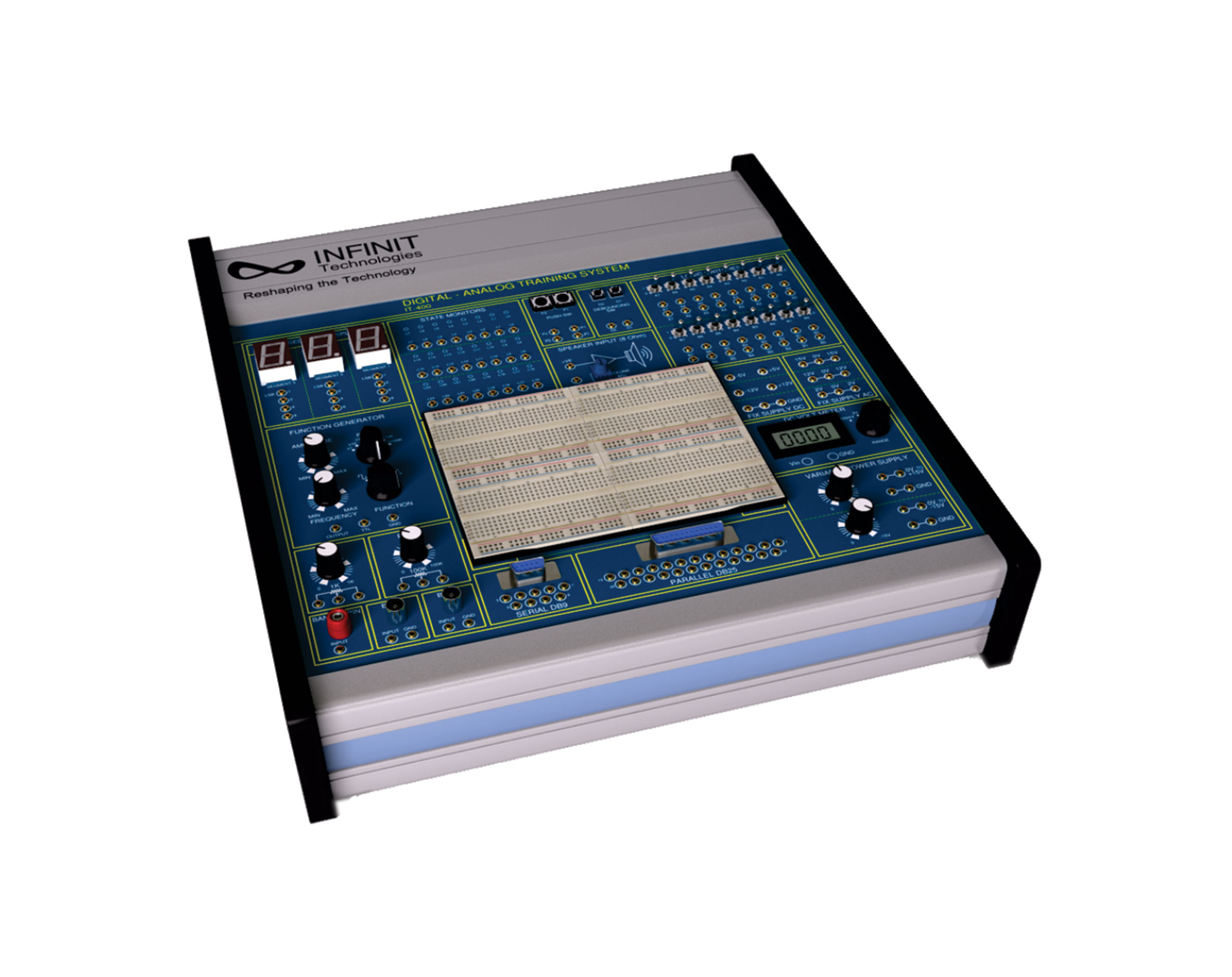
IT-400A is a comprehensive and self-contained system suitable for anyone engaged in Digital and Analog circuit experiments. All necessary equipment for Digital and Analog circuit experiments such as power supply, function generator, Data Switches, LEDs, Logic Probe, 7-Segment Displays etc are installed on the main unit. The Bread board allows students to perform a wide variety of experiments relating to essential topics in the field of digital and analog circuit. It is a time and cost saving device for both students and researchers interested in developing and testing circuit prototypes.
Features:
- Bread Board Based
- Power Supplies Included
- Basic Measuring Instruments Included
- Flexibility to Perform Custom Experiments
- Output Devices like LEDs, 7-Segment and Frequency Counter Included
- Input Devices like Push Switches, Toggle Switches Included
- Standard Function Generator Included
- User can attach custom Devices through Universal Connector detachable Cards
- Passive Components Included
- Protection Circuits Included
Technical Features:
Fixed DC Power Supply:
- +5V, -5V, +12V, -12V with short circuit protection
Variable DC Power Supply:
- 0 ~ +15V and 0 ~ -15V adjustable with short circuit protection
FIX Supply AC:
- 2V-0-2V, 12V-0-12V, 15V-0-15V with fused protection
Function Generator:
Output Waveform:
- Sine, Square, Triangle and TTL
Output Frequency:
- up to 100KHz in five steps
- Variable frequency control
- Variable Gain control
- Variable Offset control
- Output voltage adjustable to 5V p-p
Universal Counter:
- Frequency range: 1Hz~50MHz
- Input signal: TTL or CMOS level or any level.
- Display: 4 digit 7-segment LED display.
Logic Probe:
- Logic probe for displaying logic level/pulse signal display for both TTL and CMOS level signals. MEM and PULSE section for state locking or continuous input refreshing.
3 ½-Digit Digital Voltmeter:
- 200mV, 2V, 20V, 200V
Data Switch:
- 16-bit Logic switches with straight and inverted output logic
- Output compatible with TTL/CMOS logic
Push Switch:
- Two independent Switches
- Each switch output compatible with straight and inverted Logic
De-Bounce Switch:
- Each switch output is TTL compatible with De-Bounce circuit
Logic Indicator/State Monitor:
- 24 independent LEDs indicate high and low logic state
- All outputs are short circuit/over voltage protected
Digital Display:
- 3 independent 7-segment LED display with BCD to 7-segment decoder/driver Input with 8-4-2-1 code
- All outputs are short circuit/over voltage protected
Potentiometer:
- Carbon Track 1K and 100K
Interface Connectors:
- 2X BNC Connectors interfaced to 2mm gold plated pins
- 1X Banana Connector interfaced to 2mm gold plated pin
Audio Output
- 0.5W Speaker with Audio Amplifier and Volume Control
Buzzer:
- TTL/CMOS compatible input
- For visible indication of digital outputs
Optional Interface Cards:
- Universal add-on interface cards
Solderless Breadboard:
- 2 Terminal Strips, Tie-point 1680
- 4 Distribution Strips, Tie-point 400
Accessories: 2mm-1mm patch cords, Power Cord, User Manual