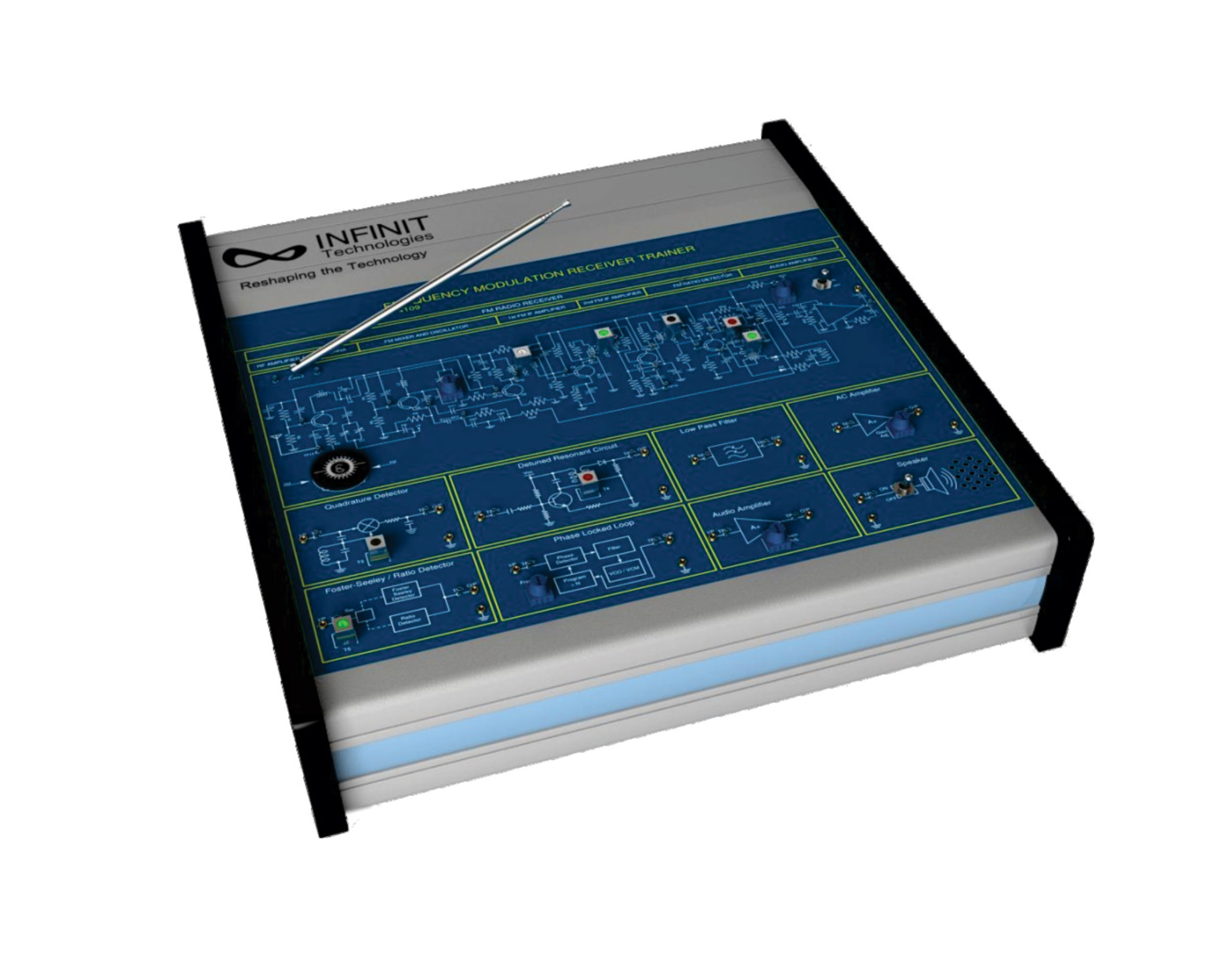
IT-4109 is designed to analyze the Techniques of Frequency De-Modulation using Analog signals. Trainer also contains an FM Radio Receiver with AFC. Frequency demodulators are also included to study the wired Frequency De-modulation techniques.
Features:
- Power Supply Included
- Required Circuits Tested
- Each Section Clearly Marked for Input and Output
- Each Section Works as an Independent Unit
- Input Devices like Antenna and RF Amplifier Included
- Output Devices like Speaker and Low Pass Filter Included
- Complete FM Radio Receiver Included
- FM Demodulation Techniques Explored
Technical Features:
FM Demodulator Types:
- Detuned Resonant
- Quadrature Detector
- Foster -Seeley
- Ratio – Detector
- Phase Locked Loop
- FM Radio
- Carrier Frequency: 455 KHz
- Low Pass Filter: 5th Order Butterworth @ 3.4 KHz
- Amplifier: AC Amplifier with adjustable gain
- Audio Amplifier: Monolithic Type
- Speaker: 8 Ohm with ON/OFF Control
FM Radio
- Sensitivity: <150mV
- FM Tuning Range: 88-108MHz
- FM IF: 10.7MHz
- Detector: Ratio Detector
- IF Amplifier 1: First FM IF Amplifier
- IF Amplifier 2: Second FM IF Amplifier
- Oscillator: FM Oscillator with mixer
- Amplifier: FM RF Amplifier with AFC Stage
- Antenna: FM Telescopic Antenna
- Gang: AM/FM Gang for Tuning
- Interconnections: 2 mm gold plated pins
Accessories: Power cord, Experiment Manual, Set of 2mm patch cords