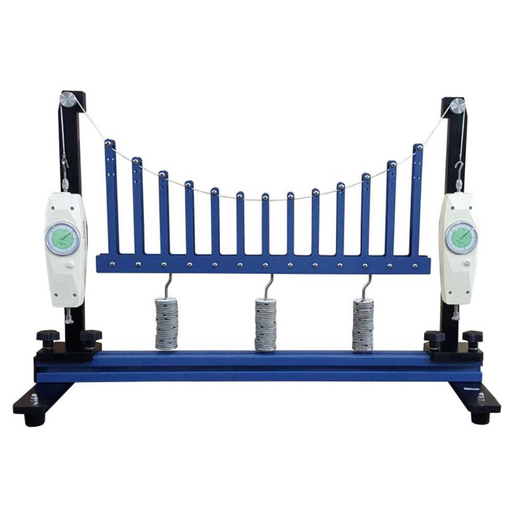
The major component of the equipment is a bridge deck with hangers suspended along its length to force a flexible steel U-shaped cable into a parabolic arc. To ensure that the bridge is steady, the suspension wire passes across pulleys and is connected to force gauges. A variety of weights, each with a unique loading value, are used to load the bridge. Known weights that are simple to place on the bridge deck can be used to provide point loads. The oldest types of bridges are suspension bridges. They are supported mostly by a flexible cable. Wide – span suspension bridges can be constructed because cables can withstand large tensile forces while having little dead weight themselves. This enables longer spans to be crossed without the need for pillars, such as across deep gorges. Due to the load being coupled to the main supporting cables through vertical cables at very frequent, consistent intervals, the sag of suspension bridge cables has a parabolic form. The SM-1419 experimental setup represents a suspension bridge. A roadway is suspended between two parallel supporting cables that make up the bridge. Vertical cables are U-shaped hangers. They hold the road in place by being attached to the primary supporting cables at regular intervals. Pylons are deflection rollers. The roadway acts as a dispersed load on the supporting wires and can be loaded with extra weights. In the center, there is a hinge. The hinge makes it possible to visualise internal moments in the road that result from uneven loading—the road buckles. Force gauges are used to calculate the tensile forces in the supporting cables. It is feasible to imitate fixed roadway supports using two supports. There are force gauges in the supports. The load distribution between the supports and the supporting cable is examined using the force gauges. The experiment’s component parts are all neatly organized and safely stored in a storage system. The frame contains the entire experimental setup. The comprehensive course materials outline the foundations and offer a step-by-step description of the experiments.
Experiments:
- Familiarisation with a suspension bridge.
* under dead-weight
* under additional load
* under evenly distributed load
* under unevenly distributed point loads - Calculation of the supporting cable force.
- Comparison between calculated and measured values of the supporting cable force.
- Observation of the effect of internal moments in the roadway under uneven load.
- Load distribution between roadway support and supporting cable.
Specifications:
- Investigation of a suspension bridge in various load cases.
- Suspension bridge with 2 supporting cables and roadway.
- Supporting cables with parabolic sag.
- Hangers (vertical supporting cables) in the form of U-shaped shackles in graduated lengths.
- Two-section roadway with central hinge.
- Roadway can be loaded by additional weights.
- Hinge in roadway indicates internal moments of roadway under uneven loading.
- Two force gauges to measure the cable force in both supporting cables.
- 2 supports with force gauges.
- Storage system to house the components.
- Experimental set-up in frame