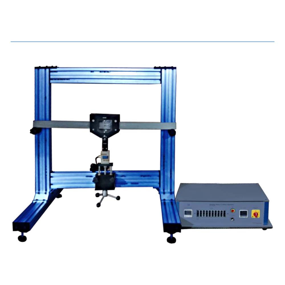
A stand-alone experiment to measure the bending stresses and strains on a T-beam. An inverted aluminum T-beam is positioned on knife edges between two basic supports. Using a fine screw jack mechanism with an integrated load cell, the load is applied to the T-beam. The placement of the load cells and the supports result in a three-point loading. On the T0-beam specimen, a number of precise strain gauges are mounted. For output stability, these strain gauges are coupled with temperature correction dummy gauges. For precise connection to the display unit, each pair of strain gauges is given a number. The display device receives the signals from the loading mechanism and strain gauges directly. A comprehensive instruction manual for the lecturer and the students that provides complete details on the assembly and use of the apparatus as well as sample results. All required assembly and working tools are included.
Experiments
- Bending Stresses across a T-Beam section.
- Comparison of theory with experimental results.
- Working with Strain gauges.
- Bending equation.
- Neutral axis.
- Working with stresses and strains and their conversion.
- Second Moment of Area.
Specifications
- T-Beam to have strain gauges attached in measuring and temperature compensation pairs.
- 500N load cell to apply load with integral cable for connection to display unit.
- Angle of load to be adjustable.
- Multiple load positions along T-Beam span available.
- Strain gauge outputs to be made available to display unit.
- Comprehensive instruction manual provided.