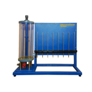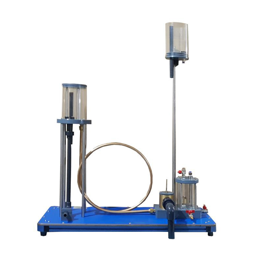
Suddenly stop of water flow can cause water hammer in the pipeline. This generally undesired effect is used specifically in special equipment (hydraulic ram) to raise water to a higher level. Unlike conventional pumps, no additional mechanical drive is required here.
This apparatus is used to demonstrate the formation and effect of water hammer and to study how a hydraulic ram working. The water is fed to the ram via a long pipe. Above a certain water velocity the waste valve in the ram closes automatically, due to the flow forces. This happens suddenly, so that the kinetic energy of the water in the pipe is converted into potential pressure energy. The pressure opens a check valve and the water flows into an air vessel. The air cushion in the air vessel dampens the water hammer and ensures a uniform lift into the elevated tank. After the water hammer has subsided, the waste valve opens due to the dead weight, the water in the pipe starts to flow again and the process repeats itself. The operation of the waste valve as a function of the weight load, the valve lift and the flow rate is studied. Furthermore, it is possible to shown how the volume of air in the air vessel affects the lift. Valves are used to adjust the flow rate. Transparent tank, a visible check valve in the air vessel and the visible movement of the waste valve all permit excellent observation of the function. All components are clearly mounted on a front plate. The water is supplied and flow rate measured by the hydraulic bench or the experimental unit can be operated by the laboratory supply.