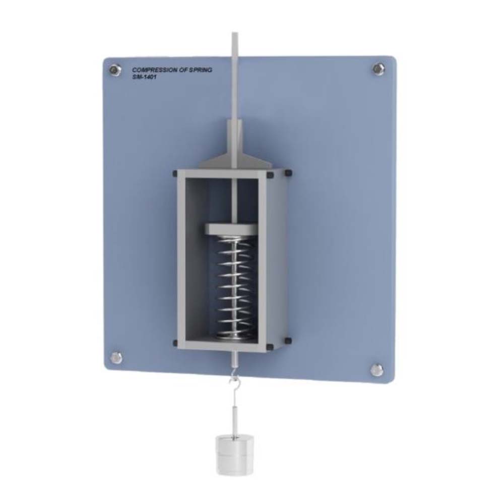
In engineering, springs are used to store energy or to supply restoring forces. It’s possible to run into both compression and tension (extension) springs. Hooke’s Law states that a spring’s deflection is dependent on the weight placed on it (Within the limit of proportionality, the strain is directly proportional to the stress producing it). Spring applications include automotive suspensions, which use them to absorb energy from wheel vertical movement brought on by potholes and bumps, and spring balances, which use spring deflection measurements to determine loads. A Aluminum anodized wall mounting housing is mounted to a wall or structure. Compression spring rests flat against the lower inner horizontal surface of the housing and has industry standard ground ends. A profiled boss connected to the load hanger rests at the top of the spring. The chamfered face of the profiled boss ensures that the spring will load in the middle and allows for the use of springs with different diameters. The wall housing is coupled to a built-in vernier scale. This provides a precise indicator of the spring compression being applied. A compression indicator is fastened to the load hanger’s shaft. To make sure the compression can be read off the vernier scale, this has a horizontal reference line. To modify the start position of compression and to account for various lengths of compression spring that might be employed, the indicator can be moved up and down the length of the load hanger. The load hanger has a solid basis that enables the device’ supplied calibrated weights to be suspended without risk. Students gauge the spring’s compression at each load interval A load versus compression graph is produced using these results, and the spring constant is computed. The learner is also given the option of measuring the spring’s essential dimensions and calculating the spring constant numerically using the formulas provided. The apparatus will come with a comprehensive experimental manual that includes the reference data.
Experiments
- To test the relationship between the load applied and the change in compressive length of a spring (Hook’s Law).
- To determine spring stiffness using measured experimental results and formulae provided.
- Load versus compression graphs.
- Action of springs.
- Using the compressive spring set, the dependence of spring stiffness on the wire diameter, spring diameter, length, number of turns and material can be observed and calculated.
- Comparison with theoretical estimate and manufacturer’s data
Specifications:
- Determination of spring stiffness.
- Wall mounted compact unit to test springs.
- Different compression spring supplied (Wire Diameters, length, no of turns).
- Load applied to spring using calibrated weights set and hanger.
- Integral compression scale (vernier scale).
- Adjustable compression indicator