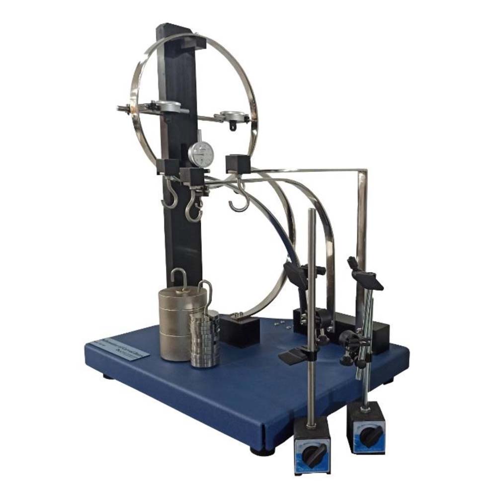
The purpose of this setup is to show how a curved bar deflects. The device uses a dial gauge that is fixed to the frame to determine the degree of deflection. Thus, in order to calculate the overall mechanical displacement of constructions that use curved sections, it is crucial to examine how curved bars deflect. The first theorem of Castiglione or the unit-load approach are two of the more useful techniques for estimating deflections in curved bars. A distinction between beams and arches is made in construction engineering. A construction with a curved axis and two fixed support bearings or clamp fasteners is referred to as an arch. A double-articulated arch’s support bearings can withstand forces both vertically and horizontally. The arch’s ends in the hinges do not move. This causes the system’s static arching effect. Crane hooks and chain links are common examples of curved beams in mechanical engineering. Five separate beams make up SM-1407, all of which are supported by statically fixed supports: a circular beam, a semicircular beam, a quadrant beam, a right angle beam, and a curved davit. A number of weights are loaded onto the beam being tested. Dial gauges capture both vertical and horizontal deformations. The second moment of area for all 5 beams has the same cross-section as well. This makes it possible to compare test results side by side. Beams that are both semi-circular and circular are fastened to a bearing on the pillar. A bearing block is used to fasten the quadrant beam. The experiment’s various components are all organised nicely and kept safe in a box.
Experiments:
- Bending behaviour of a curved-axis beam.
* circular beam
* semi-circular beam
* quadrant beam
* curved davit beam
* right angled beam - Application of the principle of virtual forces (the force method) to calculate deformation.
- Second moment of area.
- Comparison of calculated and measured Deformations.
Specifications:
- Elastic deformation of curved-axis beams under load.
- 5 different beams with the same cross-section: circular beam, semi-circular beam, quadrant beam, curved davit beam and right angled beam.
- Bearing block to fix the beams.
- Pillar with bearing to support the circular beam.
- 1 set of weights to place the beam under load.
- 3 dial gauges to record the horizontal and vertical deformation.
- Box to house the components