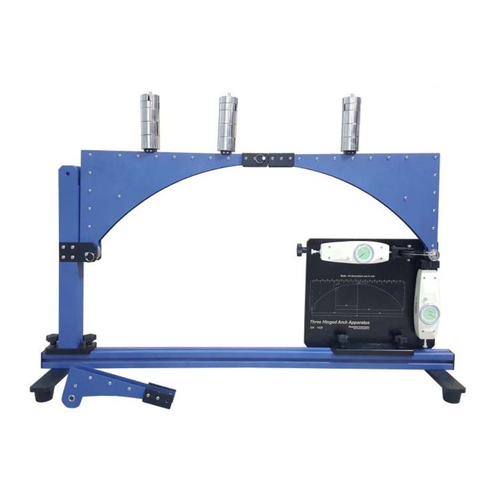
In this apparatus, a flat bridge deck is created using two equal arches. The three hinges are made when the arches are hinged at their outermost ends and at the crown hinge in the center. To investigate the pattern, known weights can be used on two different sites. Vertical and horizontal forces can be absorbed by hinges with fixed supports. The crown hinge at the centre renders the entire arrangement statically determinate. Three-hinged arches are a common design choice for bridges. When compression-proof building materials are available, this form of construction is especially suitable. At the supports of the arch, there is a horizontal thrust. Compared to a beam on two supports with the same span, it allows substantially lower bending moments in the arch. This effect is brought about by a strong longitudinal compressive force acting in the arch. A three-hinged arch is made composed of a curved beam installed on two fixed supports, typically with the ‘crown hinge’ at the top. Abutment hinges, which are the hinges on the two permanent supports, are hinges that can withstand both vertical and horizontal forces. The springing line serves as their connecting line. The system becomes statically determined thanks to the crown hinge. The SM-1420 consists of two long and one short arch segments, each of which is connected by a hinged joint to create a symmetrical or asymmetric three-hinged arch. The arch under inquiry might be loaded from different directions or from a single point. Weight settings account for an abutment hinge’s support reactions, allowing comparisons to be made between calculated and actual measured values. The experiment’s component parts are all neatly organised and safely stored in a storage system. The frame contains the entire experimental setup. The comprehensive course materials outline the foundations and offer a step-by-step guide through the experiments
- Experiments:
- Familiarisation with three-hinged arches (unsymmetrical and symmetrical).
- Application of the method of sections and the conditions of equilibrium to calculate the bearing forces for
* point load, distributed load, moving load - Investigation of the influence of the load on the horizontal thrust in the supports.
- Determination of the lines of influence for the supports under a moving load.
- Comparison of the calculated and measured support reactions for static and moving load.
Specifications:
- Investigation of 2 statically determinate three hinged arches.
- 3 arch segments: 2x long (together making a symmetrical arch), 1x short (together with 1x long: unsymmetrical arch).
- Hinged arch with 3 hinges: 1 crown hinge, 2 abutment hinges at the bearing points.
- Arch subjected to point load, distributed load (each by weights) or moving load.
- 4 sets of weights to compensate for the support reactions of an abutment hinge.
- Storage system to house the components.
- Experimental set-up in frame.