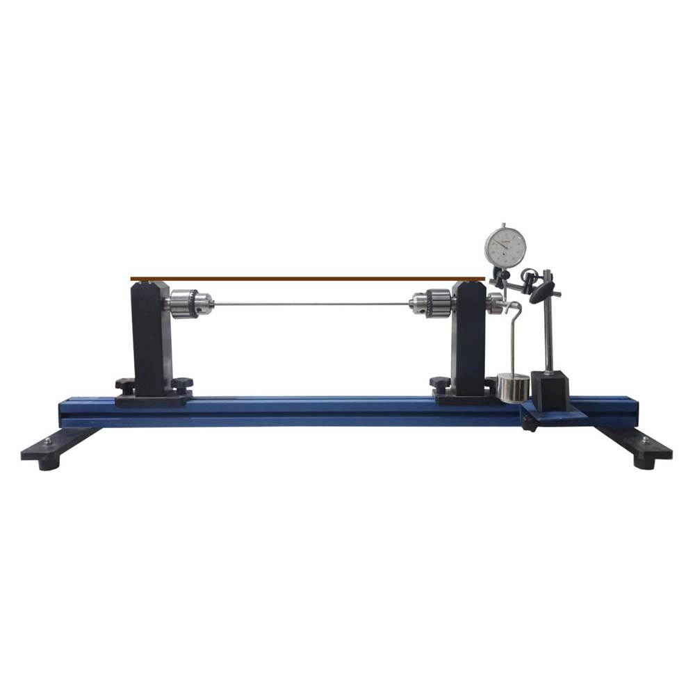
A beam is a structural component that resists bending primarily to support loads. Compressive, shear, and tensile stresses are experienced internally by the beam. In both construction and mechanical engineering, beams are important structural components. A beam is a bar-shaped structural element that is loaded both parallel to and perpendicular to its longitudinal axis. Its cross-sectional dimensions are significantly lower than its length. The force perpendicular to the longitudinal axis results in bending of the beam, which is a deformation of the beam. The beam is viewed as a one-dimensional model based on its size. The apparatus is used to measure the deflections and slopes of a beam that is bending and to compare those readings to those obtained from the differential equation and Area Moment Method calculations. Torsional vibration is the angular vibration of an object along its axis of rotation, typically a shaft. Torsional vibration can result in problems if it is not regulated in power transmission systems that involve rotating shafts or couplings. The student is able to comprehend rotating vibration torsion bars due to the combined bending and torsion of bars unit. Essentially, the unit is a bench top base frame. Torsion bar is held in place by chucks. The torsion bar has a mass hanger and load attached to one end of it. A typical load that components experience is torsion. The resulting stresses and deformations may cause the component to fail. This is affected by a variety of variables, including the bearing support technique, clamping length, bar cross-section, and material. This apparatus examines how these elements affect a bar’s twisting under bending load or torque. For both bending and torsion studies, a set of test bars has been put together in order to allow for direct comparison of measurement findings. The bar under investigation is loaded down by a weight and fastened to two movable support blocks. The resulting deformation is measured using a dial gauge. The support blocks include clamping chucks to hold the torsion bars and bearings for the bars in the bend test. Various clamping options are available with the bearings. The experiment’s components are all organized clearly and secured in a storage system. On the frame is put up the entire test setup. The well-structured instructional material sets out the fundamentals and provides a step-by-step guide through the experiments. When the torsion of the bar is not being used, the bending load can be applied to the beam. Deflection is noted when the beam is loaded.
Experiments:
- Investigation of the deflection for statically determinate straight beams
* cantilever beam
* single-span beam
* formulation of the differential equation for the elastic line - Deflection on a cantilever beam
* measurement of deflection at the force application point - Influence of the material (modulus of elasticity) and the beam cross-section (geometry) on the elastic line.
- Determination of the shear modulus of various materials.
- Angle of twist dependent on
* Clamping length
* Bar diameter - Formulation of proportional relationships for the angle of twist.
Specifications:
- Elastic lines of statically determinate under various clamping conditions of single span beam.
- Beams are availible in different materials and different dimmensions.
- 2 support with clamp fixing and dill chuck with bearing.
- 1 set of weight with adjustable rider.
- Aluminium section frame housing the experiment.
- Storage system to house the components.
- 1 dial gauge to record deformations with dial gauge support, dial gauge 0-20mm, least count 0.01mm.