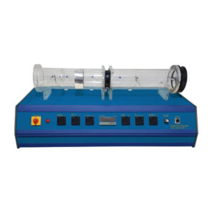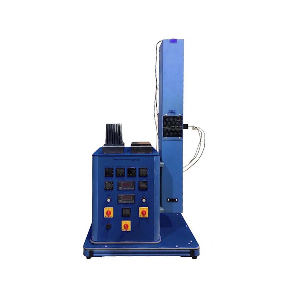
Heat transfer by Free & forced Convection in a vertical duct is carried out in this unit. Convection is one of the three basic types of heat transfer. In this process, the whole fluid moves from warm zones into cold zones. The vertical duct is constructed in such a way that the air temperature and velocity can be readily measured. A fan situated at the top of the duct provides the air stream for forced convection experiments. A control panel contains temperature measurement, power control, and fan speed control circuits with appropriate instruments. Air velocity was measured with a portable anemometer mounted on the duct. Heat transfer by simultaneous conduction and convection, whether free or forced, forms the basis of most industrial heat exchangers and related equipment. The measurement and prediction of heat transfer coefficients for such circumstances are achieved in the Free & Forced Convection Heat Exchanger by studying the temperature profiles and heat flux in an air duct with associated flat and extended transfer surfaces. The vertical duct is so constructed that the air temperature and velocity can be readily measured, and a variety of .plug-in. modules of heated solid surfaces of known dimensions can be presented to the air stream for detailed study. A fan situated at the top of the duct provides the air stream for forced convection experiments. A Control Panel contains temperature measurement, power control, and fan speed control circuits with appropriate instrumentation. Temperature measurement, to a resolution of 0.1o C, is effected using thermocouple sensors with direct digital read-out in o C. Air velocity is measured with a portable anemometer mounted on the duct. The power control circuit provides a continuously variable, electrical output of 0-100 watts with a direct read-out in watts. Using the instrumentation provided, free and forced convective heat transfer coefficients may be determined for:-
1. A flat surface
2. An array of cylinders (tubule bundle)
3. An extended finned surface
4. A plate surface (optional)
5. A cylinder (optional)
6. A cylinder with heating foil to investigate local heat transfer (optional)
Each module may be used independently on the bench, to establish free convection coefficients for horizontal orientation. The apparatus is fully self-contained.