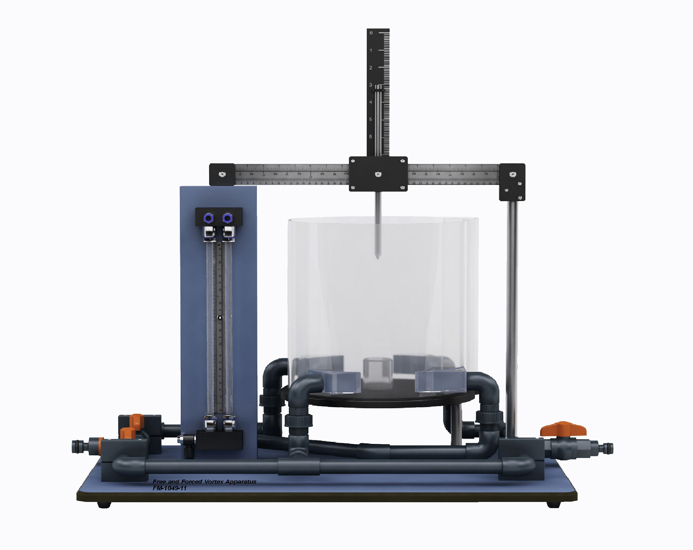
The Free and Forced Vortex apparatus has been designed for students to experiment to produce and measure free and forced vortexes. It consists of a clear acrylic cylinder where the free vortex is generated by water discharging through an interchangeable orifice in the base of the cylinder. The resulting profile is then measured using a combined sliding and depth scale. The forced vortex is induced by a paddle rotated by jets of water at the cylinder base. The profile of the forced vortex is then determined using a profile-measuring gauge. Velocity at any point in the free or forced vortex may be measured using the pitot tube supplied.
The apparatus is designed to be positioned on the hydraulics bench. The apparatus consists of a cylindrical vessel having two pairs of diametrically opposed inlet tubes. Overflow cut-outs ensure a constant level in the tank during experiments. A smooth outlet is centrally positioned in the base of the vessel, and a set of push-in orifices of various diameters are supplied. The 12mm diameter inlet tube, which is angled at 15 degrees, imparts a swirling motion to the liquid entering the vessel and is used as an entry tube for the free vortex experiment. The forced vortex is created by using the 6mm inlet tubes which are angled at a tangent to the diameter.
The input from these tubes impinges on a paddle that acts as a stirrer/flow straightener. The paddle rotates on a stud mounted on a bushed plug inserted in the central orifice. A bridge piece incorporating a profile measuring gauge is used to determine the profile of the forced vortex. The needle can travel along X and Y Axis on a pre-calibrated scale so a virtually infinite position of the vortex can be drawn rather than the fixed point measurements. Velocity heads may be visualized by the insertion of a pitot tube in the vortex at any point.