|
|
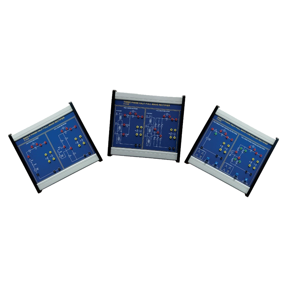
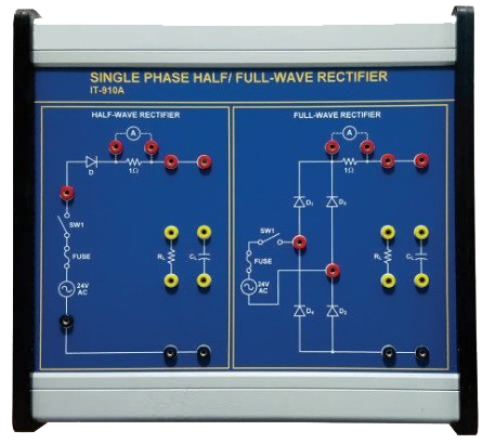
| Single Phase Half, Full-Wave Rectifier IT-910A
Experiment:
- You may understand the principle and characteristic commutation circuit converting the AC to DC by using the diode characteristic.
Technical Data:
- Input Power: AC 220V
- Output Load: Resistance Load 10W 10o ohm
- Diode: 600V 10A
- Input AC Wave, Output Voltage Wave
- Check Terminal: Measures output current and
diode counter voltage.
|
 |
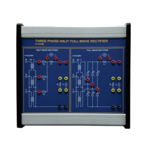
| Three Phase Half/Full-Wave Rectifier IT-910B
Experiment:
- You may understand principle and characteristic of 3-phase commutating circuit through the experiment to get the complete DC output from the 3-phase AC Voltage by using the characteristic of diode.
Technical Data:
- Input Power: AC 3-phase 380V
- Output Load: 10W 100ohm
- Diode: 600V 10A
- Check Terminal: Measuring input AC Wave output voltage wave, output current.
|
 |
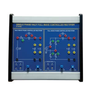
| Single Phase Half/Full-Wave
Phase Controlled Rectifier
IT-910C
Experiment:
- Understanding the principle of phase control and characteristic of SCR through the experiment on phase control of commutating circuit and gate circuit, and characteristic of SCR.
Technical Data:
- Input Power: AC 220V
- Output Load: 10W 100ohm
- SCR Module: 100V 10A
- Drive IC: SCR gate trigger circuit.
- Check Terminal: Measuring the input AC Wave.
- Output voltage wave.
- Output current and counter voltage of SCR
|
 |
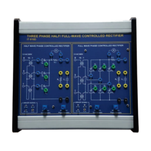
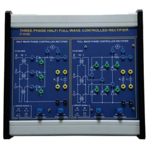
IT-910D
Three Phase Half/Full-Wave Phase Controlled RectifierExperiment: Understanding the principle of phase control and characteristic of SCR through the experiment on phase control of commutating circuit and gate circuit, and characteristic of SCR.Technical Data:
- Input Power: AC 220V
- Output Load: 10W 100ohm
- SCR Module: 100V 10A
- Drive IC: SCR gate trigger circuit.
- Check Terminal: Measuring the input AC Wave.
- Output voltage wave.
- Output current and counter voltage of SCR
|
 |
| Buck (Step-Down) Converter
IT-910E
Experiment:
- Experiment to acquire the higher output voltage by returning the energy accumulated at the position of L of the power source.
Technical Data:
- Input Power: AC Single-phase 220V
- Output load: 10W 100 ohm
- GBT: 1000V 25A
- Drive IC: IGBT Gate trigger circuit
- Check Terminal: Measures the input voltage, current wave.
- Output Voltage wave and output current.
|
 |
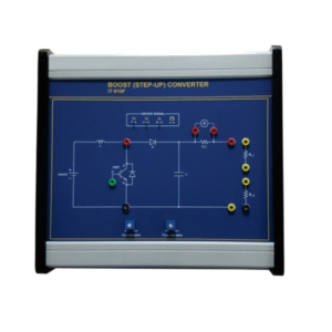
| Boost (Step-Up) Converter
IT-910F
Experiment:
Experiment to acquire the higher output voltage by returning the energy accumulated at the position of L of the power source.
Technical Data:
- Input Power: AC Single-phase 220V
- Output load: 10W 100 ohm
- GBT: 1000V 25A
- Drive IC: IGBT Gate trigger circuit
- Check Terminal: Measures the input voltage, current wave.
- Output Voltage wave and output current.
|
 |
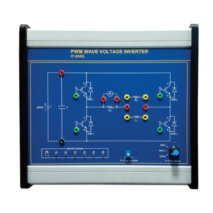
| PWM Wave Voltage Inverter
IT-910G
Experiment:
- The Experiment to acquire AC output which is more closer to sine wave by providing the control output for converting DC Voltage to AC Voltage in the form of PWM.
Technical Data:
- Input Power: AC Single-phase 220V
- Output Load: 10W 100ohm
- GBT: 1000V 25A
- Drive IC: IGBT gate trigger circuit
- Check Terminal: Measures input voltage, current wave.
- Output voltage wave and output current.
|
 |
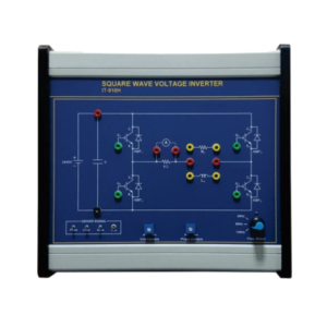
| Square Wave Voltage Inverter
IT-910H
Experiment:
Experiment on AC Load by authorizing the control signal for converting the current voltage to AC voltage as the square wave.
Technical Data:
- Input Power: AC Single-phase 220V
- Output Load: 10W 100ohm
- GBT: 1000V 10A
- Drive IC: SCR gate trigger circuit.
- Check Terminal: Measures the input voltage, current wave.
- Output voltage wave and output current.
|
 |
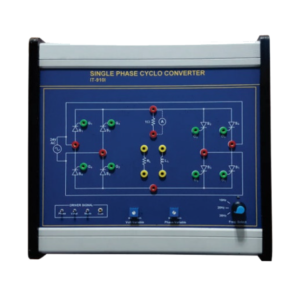
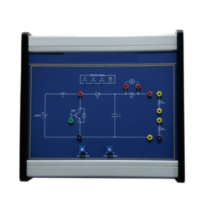
| Single Phase Cyclo-Converter
IT-910I
Experiment:
- Experiment on the frequency converter converting the AC Power of input frequency to the other AC Power directly
Technical Data:
- Input Power: AC Single-phase 220V
- Output Load: 10W 100ohm
- GBT: 1000V 25A
- Drive IC: SCR gate trigger circuit.
- Check Terminal: Measures the input voltage, current wave.
- Output voltage wave and output current.
|
 |
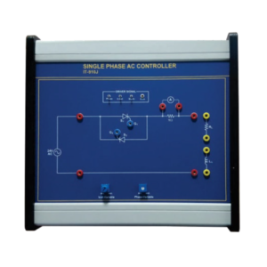
| Single Phase AC Control
IT-910J
Experiment:
Experiment on AC output control by changing the voltage value through the control of phase when the induction motor and AC output are required.
Technical Data:
- Input Power: AC Single-phase 220V
- Output Load: 10W 100ohm
- GBT: 1000V 10A
- Drive IC: SCR gate trigger circuit.
- Check Terminal: Measures the input voltage, current wave.
- Output voltage wave and output current.
|
 |
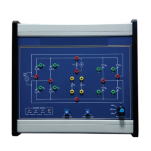
| 3-Phase Inverter
IT-910K-1
Experiment:
- Discrete control from single high frequency clock. (9.6KHz)
- Three phase generation with 120 degree inter phase angle delay from Johnson Counter technique.
- Each phase sine generation with PWM technique.
|
 |
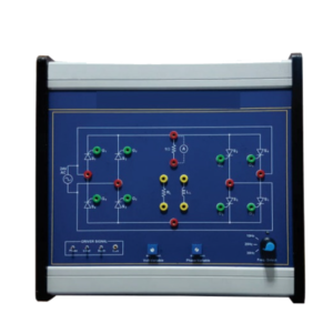
| 3-Phase Inverter IT-910K-2
Experiment:
- Experiment on 3-phase inverter with IGBT module.
Technical Data:
- Input Power: AC Single-phase 220V
- Output Load: 24VA
- MOSFET driver: 55V, 49Amp
- Check Terminal: Measures the output voltage, current / observe PWM signal at driver input.
- Output voltage and current three phase: 40V (line voltage)
|
 |
IT-910M Motor Module
- Universal speed control system.
- With integrated four-quadrant display.
- With variable centrifugal mass.
- Dual-channel encoder.
- Built-in four-quadrant amplifier.
Technical Features:
- Linear H bridge to have full motor control
- Dual optical sensor for speed and direction
- Main Motor/Generator 12 V, 3000 rpm, 1.2 A, 3.2 Ncm
- Load to be connected to the secondary Motor/Generator
- Shunt to limit and measure the current
|
 |