Experiments

  • Determination of the dimensional characteristic curves for different types of pumps.
  • Determination of the specific speed of different types of pumps.
  • Verification of the similarity rules for pumps of different geometry.

 Additional practical possibilities:

  • Sensors calibration.

Centrifugal Pump:

  • Determination of the curve Q vs r.p.m. of the centrifugal pump.
  • Determination of the curve H vs Q for different r.p.m. of the centrifugal pump.
  • Determination of the mechanical power vs flow for different r.p.m. of the centrifugal pump.
  • Determination of the curve η vs the flow for different r.p.m. of the centrifugal pump.
  • Determination of the characteristics map of a centrifugal pump.

Turbine Pump:

  • Determination of the curve Q vs r.p.m. of the turbine pump.
  • Determination of the curve H vs Q for different r.p.m. of the turbine pump.
  • Determination of the mechanical power vs flow for different r.p.m. of the turbine pump.
  • Determination of the curve η vs the flow for different r.p.m. of the turbine pump.
  • Determination of the characteristics map of a turbine pump.

Gear Pump:

  • Determination of the curve Q vs r.p.m. of the gear pump.
  • Determination of the curve H vs Q for different r.p.m. of the gear pump.
  • Determination of the mechanical power vs flow for different r.p.m. of the gear pump.
  • Determination of the curve η vs the flow for different r.p.m. of the gear pump.
  • Determination of the characteristics map of a gear pump.

Axial Pump:

  • Determination of the curve Q vs r.p.m. of the axial pump.
  • Determination of the curve H vs Q for different r.p.m. of the axial pump.
  • Determination of the mechanical power vs flow for different r.p.m. of the axial pump.
  • Determination of the curve η vs the flow for different r.p.m. of the axial pump.
  • Determination of the characteristics map of an axial pump.

Flexible Impeller Pump:

  • Determination of the curve Q vs r.p.m. of the flexible impeller pump.
  • Determination of the curve H vs Q for different r.p.m. of the flexible impeller pump.
  • Determination of the mechanical power vs flow for different r.p.m. of the flexible impeller pump.
  • Determination of the curve η vs the flow for different r.p.m. of the flexible impeller pump.
  • Determination of the characteristics map of a flexible impeller pump.

Diaphragm Pump:

  • Determination of the curve Q vs r.p.m. of the diaphragm pump.
  • Determination of the curve H vs Q for different r.p.m. of the diaphragm pump.
  • Determination of the mechanical power vs flow for different r.p.m. of the diaphragm pump.
  • Determination of the curve η vs the flow for different r.p.m. of the diaphragm pump.
  • Determination of the characteristics map of a diaphragm pump.

Plunger Pump:

  • Determination of the curve Q vs r.p.m. of the plunger pump.
  • Determination of the curve H vs Q for different r.p.m. of the plunger pump.
  • Determination of the mechanical power vs flow for different r.p.m. of the plunger pump.
  • Determination of the curve η vs the flow for different r.p.m. of the plunger pump.
  • Determination of the characteristics map of a plunger pump.

Specifications

  • Unit designed to demonstrate the operating characteristics of several types of pumps
  • Anodized aluminum frame and panels made of painted steel
  • The unit includes wheels to facilitate its mobility
  • Main metallic elements made of stainless steel
  • Diagram in the front panel with distribution of the elements similar to the real one
  • Fully instrumented self-contained unit

Computer controlled (Optional)
Centrifugal Pump (FM-1849-53-1)
Axial Pump (FM-1849-53-2)
Gear Pump (FM-1849-53-3)
Turbine Pump (FM-1849-53-4)
Flexible Impeller Pump (FM-1849-53-5)
Diaphragm Pump (FM-1849-53-6)
Plunger Pump (FM-1849-53-7)
Second Centrifugal pump (FM-1849-53-8)

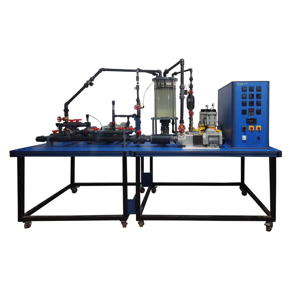
The Multi pump Testing Bench allows the students to study the operating characteristics of several types of pumps.

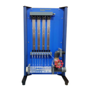
This unit allows to control and to measure the most representative parameters of the pumps. The measurements that can be taken using the unit are: admission and discharge pressure of the pump, impelled water flow, torque and turning speed of the pump and the manometric height, the hydraulic and mechanic power and the efficiency can be determined. The unit is mounted on a structure with a working surface covered by a plastic sheet. Two different parts can be distinguished in the unit: the pumps, with their motors, connections and flexible hoses and the tanks to store and recycle water, with their measuring elements.  The standard supply includes four types of pumps: one centrifugal pump, one axial flow pump, one gear pump and one turbine pump. There are several optional pumps (not included in the standard supply) that can be connected to the unit through valves and flexible hoses in order to demonstrate the operating behaviour of these pumps.

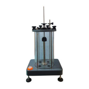
Each pump is activated by a separate motor that allows the direct measurement of the torque. The speed is changed by a frequency converter, located in the control interface box, and computer controlled. The pump under study impels water in a closed circuit. There are two pressure tappings in each pump, one at the admission and other at the discharge of the pump, to determine the manometric head of the different pumps. These tapings are connected to their corresponding pressure sensor. The pumps included in the standard supply are connected through flexible hoses to the volumetric tank and to the storage tank. The connection of the optional pumps to the volumetric tank and the storage tank are done through valves, connections and flexible hoses. The unit includes two tanks, located at different levels, to recycle the water. The upper volumetric tank, located just over the water storage tank, is equipped with two weirs and includes a discharge valve and an activator. The volumetric tank has been designed to accommodate low or high flows and it includes a level sensor to determine the water flow and the water level in the volumetric tank, an indicating transparent tube and a graduated scale. It has a safety overflow system that directly pours water into the storage tank if an incorrect use is made. The storage tank includes an indicating transparent tube.