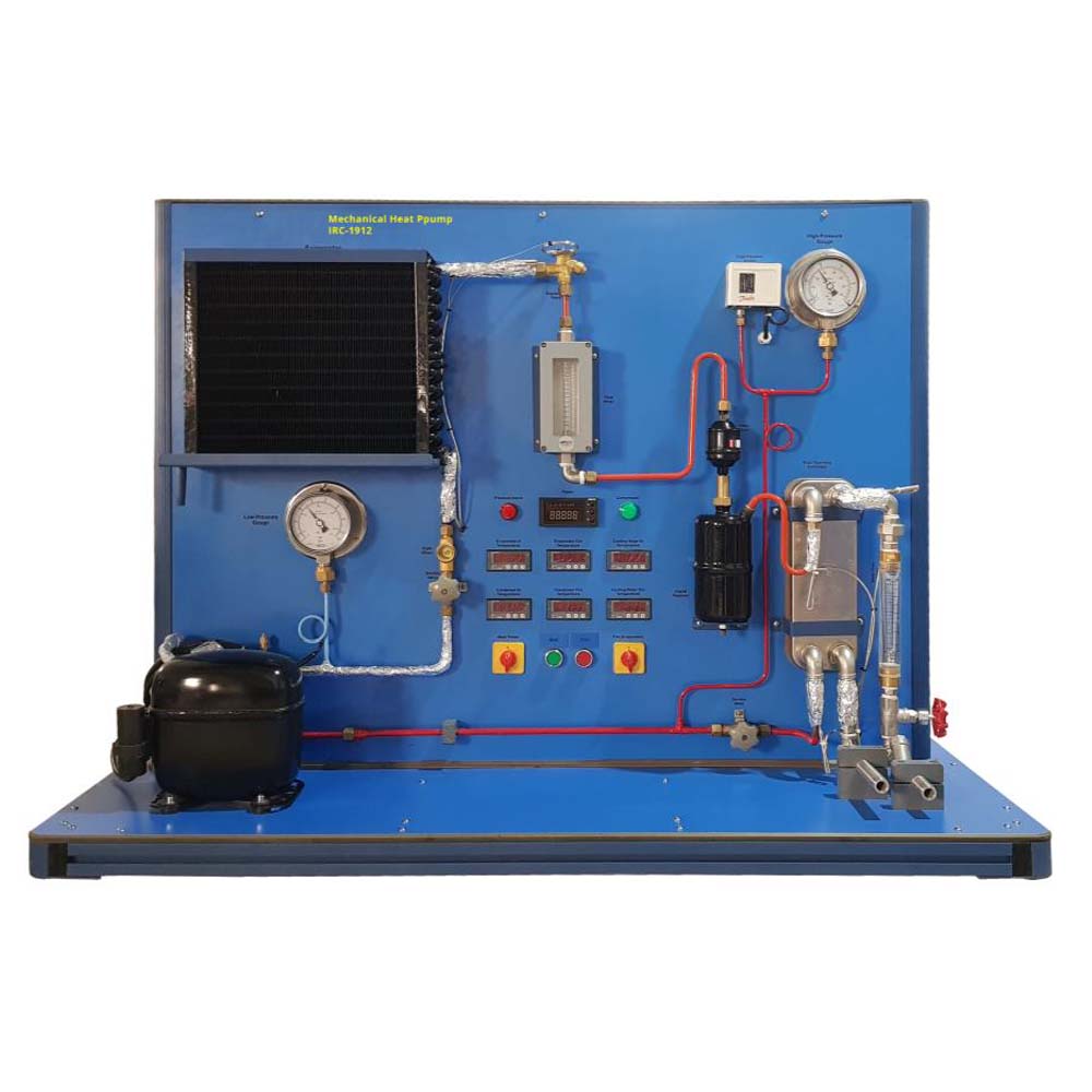
The Mechanical Heat Pump is aimed for education use and produces data in both quantitative and qualitative forms that are simple for students to understand. Students may make measurements and make calculations thanks to the equipment’s compact and appropriate instrumentation. The experiment’s goal is to illustrate how heat can be transferred from a colder object to a hotter object, which is one of refrigeration’s fundamental concepts. A typical compressor condenser unit, a watt meters, and control instrumentation comprising a flowmeter, thermocouples, and pressure gauges are all included. All of the parts and instruments for the Mechanical Heat Pump Apparatus are fixed on the stable platform, making it a stand-alone unit. A thermostatic expansion valve, a water-cooled plate heat exchanger, a hermetic compressor, and an air[1]heated evaporator make up the heat pump. The components are arranged in a similar way to how they are in many household air-water heat pumps, where they can be seen from the front of the unit. A little bit superheated refrigerant (R-134a) vapour enters the compressor from the evaporator during operation, increasing its pressure. Due to the increase in temperature, heated vapour then enters the water-cooled condenser. The refrigerant loses heat to the cooling water and turns into liquid before it reaches the expansion valve. The pressure of the liquid refrigerant decreases as it passes through the expansion valve. The saturation temperature subsequently drops below the ambient temperature as a result of this. As a result, the refrigerant and the air being drawn over the coils are at different temperatures as they pass through the evaporator. The refrigerant begins to boil as a result of the heat transfer, and when it leaves the evaporator, it is a slightly superheated vapor and is ready to go back to the compressor. The water flow rate and the water’s inlet temperature regulate the temperature at which heat is delivered in the condenser. Environmental conditions play a significant role in determining evaporation temperature. There are instruments available for measuring the flow rates of cooling water and refrigerant, the power input to the compressor, and all relevant temperatures.
Software IRC-1912SW (optional)
DAQ software specially designed in National Instrument™, LABVIEW™ environment to measure and calculate the results of apparatus. The software is optional and while using software a set of electronic sensors are included. Software can be run with any Windows™ environment.


