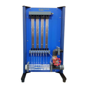
A common task in the refrigeration industry is connecting electrical components for the start and operation of refrigerant compressors. Safety considerations are also crucial. IRC-1914 makes it possible to learn these concepts and abilities. With mains voltage, all components are operated and tested to ensure high practical relevance. The electrical parts required to start and run the refrigerant compressor are organized in a way that makes them easily visible. The electrical connection of the individual components is made with cables via the lab jacks. The capacitor and start-up relay, for instance, are components required to start the motor. The front panel’s circuit schematic makes it simple to allocate the various parts. The pressure switches on the intake and delivery sides of the compressor may be checked according to the refrigeration circuit with the compressor and receiver. Valves are used to set the pressure, and a pressure switch is tripped. The monitoring of the pressure curve is made possible by two manometers. The compressor’s current supply is cut off if one of the pressure switches trips. Additionally, other standard safety chain parts like automated fuses and circuit breakers are wired and checked.

Experiments
- Read, understand, wire and test electric circuit diagrams for refrigerant compressors.
- Safety aspects when handling mains voltage.
- Design and testing of a safety chain.
- Design and operation of electrical components of refrigerant compressors
*Start-up capacitor
*Start-up relay
*Overheat protection
*Automatic fuse
*Pressure switch
*Thermostat - Representation methods in electrical engineering.
*Symbols
*Circuit diagrams
Specifications
- Correct electrical connection of a refrigerant compressor.
- Control panel inclueds test point pins provision with semplicily and installed on same panel with compressor and pressure gauges.
- Refrigerant circuit with compressor, receiver, 2 valves and 2 manometers to investigate pressure switches on the delivery and intake sides.
- Electrical components for the start and operation of the compressor mounted clearly visible.
- Lab jacks and cables to connect the electrical components.
- Operation of a thermostat.
- Circuit diagram on the front panel for easy identification of the components.
- Refrigerant R134a, CFC-free.