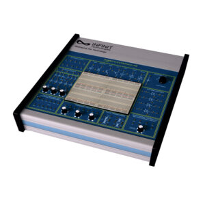
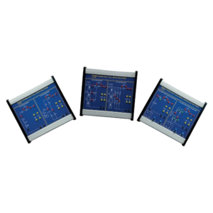
The IT-9500 Advanced Power Electronics Trainer consists of 28 experimental modules, a three-phase squirrel cage motor, load, control and measuring devices. includes single-phase rectifiers, three-phase rectifiers, DC choppers, inverters and application experiments.
Features:
The IT-9500 is the combination of power, electronics, and control. It has wide applications of solid-state electronics to the control and conversion of electric power. Popular circuits of power electronics contain rectifiers, choppers and converters. These experimental modules of IT-9500 include converter, power supply, load, control and testing modules. These experimental modules and instruments are introduced and demonstrated in the subsequent experiments.
Technical Features:
- Fixed DC Power Supply: +5V, -5V, +12V, -12V, +15 V, +35V, -35V
- Fixed AC Power Supply: 18V-0V-18V, 0V-15V
- Carbon Track Potentiometer:1M, 2x5K
- Diode: 4x1N4007
- Capacitor: 0.33uF, 0.1uF, 1uF
- Inductance: 10mH, 2X68mH
- Power Devices: 5xSCR, TRIAC, DIAC, PUT, UJT, IGBT, MOSFET
- Load Resistance Selectable: 47R/7W, 1K/1W, 1K/10W, 120ohm/5W, 2K2/2W, 270ohm/5W
- Pulse Transformer: 2X 1:1, 1:1:1
Single Phase Controlled Rectifier Firing Circuit:
- Firing angle control 0º – 180º
Triggering Circuit:
- 4 Gate Signal Output
- Frequency Range: 30Hz to 900Hz Variable
- Amplitude: 12V
- PWM control of G1, G2, G3 and G4
- Duty cycle control of “Gate”
- Signal is 0 to 100%
Solderless Breadboard:
- 2 Terminal Strips, Tie-point 1680
- 4 Distribution Strips, Tie-point 400
Accessories: Power Cord, User Manual, Experiment Manual, 2mm-2mm Patch Cord
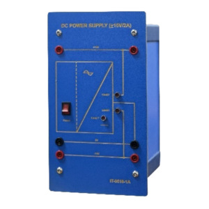
| DC Power Supply (+ 15V/2A) IT-9510-1A
1. Short circuit & over temperature protection 2. Over current indicator : LED 3. Over temperature indicator : LED 4. Rated output : ±15V/2A 5. Power indicator : yes 6. Operation power supply: AC 220V, 50/60Hz
|
 |
|
DC Power Supply (0~40V/3A, 0~20/6A) IT-9510-1B
1. Input voltage. 220VAC 2. 2 output voltage : 0-20V, 0-40VDC 3. Rated current : 0-20V/6A, 0-40V/3A 4. Overload protection
|
 |
| Reference Variable Generator
IT-9510-2A
1. Vc range: 0V~ +10V, -10V~+10V 2. External reference voltage input (VREF): ±10V 3. Output: a. 0~+ VREF b.-VREF ~0~+VREF 4. Adjustment scale : 0-100% 5. Operation power supply : ±15V
|

|
| Differential Amplifier
IT-9510-2B
1. 4 Channels output and input 2. Measuring voltage (Max.): 700Vp 3. Output voltage (Max.) : 10Vp 4. Measuring frequency (Max.) : 200KHz 5. Input voltage range : 500V, 100V, 1OV 6. Output voltage range : 10V 7. Output terminal : common ground, 3 types a. 2 BNC sockets oscilloscope, Two switches to select measuring channel (A/B, C/D) b. 2mm terminal for module connection 8. Operation power supply: AC220V, 50/60Hz |
 |
| Current Transducer
IT-9510-2C
1. Hall current sensor 2. Measuring frequency (Max.) : 200KHz 3. Current measuring : a. Input: 20Ap / output 10V b. Input: 5Ap / output 10V c. Input: 1Ap / output 10V 4. Over current indicator 5. Operation power supply : AC220V, 50/60Hz
|
 |
| Three Phase Angle Controller
IT-9510-2D
1. Pulse output: Electric isolation, directly drives up to 6 thyristors 2. Trigger angle: 0~180o 3. Control input signal: 0~10V DC 4. Rectification angle: 0~90o adjustable 5. Convert angle: 0~180o adjustable 6. Mode select: Single pulse & continuous pulse 7. Operation power supply : ±15V
|

|
|
R.M.S. Meter IT-9510-3A
1. Measuring range: a. Current. 0.1/0.3/1/3/10/20 A b. Voltage : 3/10/30/100/300/1000V 2. 3 Measuring types : a. RMS AC+DC: Total RMS value b. RMS AC: Ripple RMS value c. AV AC+DC: Arithmetic mean value 3. Overload protection 4. ±Value indicator : LED 5. Accuracy : 2% Full scale 6. Operation power supply : AC 220V, 50/60 Hz |
 |
|
Power Meter (0.3W-30KW) IT-9510-3B
1. Measuring range: 0.3W~30KW a. Current: 0.1/0.3/1/3/10/30 A rms b. Voltage: 3/10/30/100/300/1000V rms 2. Frequency range: 0-20KHz 3. Overload protection 4. Over current & over voltage LED indicator 5. Reactive power ± value indicator (QL & QC) 6. Accuracy : 2% full scale 7. Output terminal: Measuring full scale 100% =1V 8. Operation power supply: AC220V, 50/60Hz
|
 |
| Resistor Load Unit
IT-9510-3C
1. Bench top type 2. 3 load resistors, each one 100Ω 3. Rated current: 2.5A 4. Rated Power: 625W |
 |
| Resistor Load
IT-9510-3D
1. 2 Resistors load: a. 5~50Ω/120W b. 10~100Ω/120W 2. Over current protection
|
 |
| Inductive Load Unit
IT-9510-3E
1. Bench top type 2. Load indicator: 50mH x 2/200mH 3. Rated current : 5A
|
 |
| Flyback Switching Power Supply
IT-9510-4A
1. Test point : a. Switching control IC output signal b. Current feedback signal c. Voltage feedback signal d. Switching power component terminal 2. Switching frequency up to 40KHz 3. Converter control. Isolation feedback converter 4. Input voltage : 95~250V AC 5. Output : 45W, up to 80% efficiency 6. Output voltage ripple : ≤ 5% 7. Output voltage regulation : ≤ 5% 8. Output voltage: DC 10V ~ 13V, adjustable 9. Rated current: 3A Max. overload & short circuit protection 10. switching power component : MOSFET
|
 |
| Boost Switching Power Supply
IT-9510-4B
1. Test point: a. Switching control IC output signal b. Current feedback signal c. Voltage feedback signal
d. Switching power component terminal 2. Switching frequency up to ≥40KHz 3. Converter control. Isolation feedback converter 4. Input voltage: DC 10 ~ 16V 5. Output: 60W, up to 85% efficiency 6. Output voltage ripple: ≤ 5% 7. Output voltage regulation: ≤ 5% 8. Output voltage: DC 18V ~ 30V, adjustable 9. Rated current: 2A Max. Overload & short circuit protection 10. switching power component: MOSFET
|
 |
| Buck Switching Power Supply
IT-9510-4C 1. Test point: a. Switching control IC output signal b. Current feedback signal c. Voltage feedback signal d. Switching power component terminal 2. Switching frequency up to ≥40KHz 3. converter control. Isolation feedback converter 4. Input voltage: DC 17 ~ 30V 5. Output: 45W, up to 85% efficiency 6. Output voltage ripple: ≤ 5% 7. Output voltage regulation: ≤ 5% 8. Output voltage: DC 10V ~ 15V, adjustable 9. Rated current: 3A Max. Overload & short circuit protection 10. switching power component: MOSFET
|

|
| Buck Boost Switching Power Supply Unit
IT-9510-4D 1. Test point: a. Switching control IC output signal b. Current feedback signal c. Voltage feedback signal d. Switching power component terminal 2. Switching frequency up to ≥40KHz 3. Converter control. Isolation feedback converter 4. Input voltage: DC 16 ~ 26V 5. Output: 60W, up to 85% efficiency 6. Output voltage ripple: ≤ 5% 7. Output voltage regulation: ≤ 5% 8. Output voltage: DC 25V ~ 30V, adjustable 9. Rated current: 2A Max. Overload & short circuit protection 10. switching power component: MOSFET |
 |
| Electronic Ballast Fluorescent Lamp
IT-9510-4E
1. Switching frequency :10KHz 2. Input voltage range: 220V AC 3. Type of lamp: Fluorescent Tube 4. Control mode: half-bridge self-excitation feedback multivibrator 5. Output current: 3A max. with overflow ” and short circuit protection 6. Switching power component: BJT
|
 |
| IGBT Drive Set IT-9510-4F
1. Input voltage: DC 20~300V 2. Output voltage: 20~300Vp 3. Drive circuit : Photo couple and drive circuit 4. Output device : IGBT, 800V/60A 5. Current detector & protector: Hall effect
|
 |
| DC PWM Generator
IT-9510-4G
1. Triangular wave (carrier) generator a. Amplitude: 0~10V or -10~+10V b. Frequency: 1K, 10K, 15KHz 2. PWM signal generator 2 x PWM control signal 3. IP input: DC-10V~+10V 4. Operation power supply: DC ±15V
|
 |
| Single Phase PWM Controller
IT-9510-4H
1. Triangular wave (carrier) generator a. Amplitude: -10V~+10V b. Frequency: 1K, 5K, 15KHz 2. Sine wave signal generator 3. Multiplex 4. PWM Signal generator: 2 x TTL level 5. Square wave signal generator 6. IP input: DC 0V~+10V 7. Operation power supply : DC±15V
|
 |
| Three Phase PWM Controller
IT-9510-4I
1. Triangular wave (carrier) generator a. Amplitude: -10V~+10V b. Frequency: 5K, 10K, 20KHz 2. Sine wave signal generator 3. Multiplex 4. PWM Signal generator: 6 x TTL level 5. Square wave signal generator 6. IP input : DC – 10V~+10V 7. Operation power supply : DC±15V |

|
| Three Phase Rectifier & Filter
IT-9510-4J
1. Power input : 1Ø or 3Ø, 0~220V AC 2. With Inductor & capacitor filter circuit 3. Surge protection in voltage circuit 4. 28~300V DC (max.)/10A (max.) |
 |
| Universal Inverter 3x230V
IT-9510-4K
1. 6 x TTL level signal input: > 2.5μS, for interlock & dead time control 2. Power input: 30~300 DC 3. With photo-couple, isolation and main circuit 4. Output power component: IGBT 800V/60A 5. With adjustable over current protection circuit 6. Output capacity: 220V/ 1.5kW 7. Operation power supply: AC 220V, 50/60 Hz
|
 |
| Power Diode Set
IT-9510-5A
1. Rated voltage: 1200V 2. Rated current: 40A |
 |
| Fuse Set
IT-9510-5B
1. Module design 2. 3 x D-Type fuses, 500V/6A
|
 |
| Thyristor (800V/10A)
IT-9510-5C
1. Rated voltage : 800V 2. Rated current : 10A 3. With RC surge buffer protection circuit
|
 |
| SCR / TRIAC Set
IT-9510-5D
1. SCR : 800V/16A 2. TRIAC : 600V/12A 3. Load lamp: 2 x 12V/10W (with switch) 4. Load inductor: 1 x 50 mH/1A (with switch) 5. With currents voltage transfer measurement 6. With trigger control adjustable 7. Operation power supply AC 220V, 50/60 Hz
|
 |
| MOSFET/ IGBT Set
IT-9510-5E
1. IGBT: 800V/ SOA 2. MOSFET: 100V/48A 3. Load lamp: 2 x 12 V/ 10W (with switch) 4. Load inductor: 1 x 50mH/1A (with switch) 5. With current/voltage transfer measurement 6. With trigger control adjustable 7. With external signal input 8. Operation power supply : DC±15V |
 |
| SCR DC Chopper Set
IT-9510-5F
1. Operating voltage : ±15V, 0.4A 2. Input voltage range : 50V~300V DC 3. Maximum output current: 5A 4. Chopping frequency range: 220Hz ~ 280Hz 5. Minimum duty cycle: 0.1 6. Maximum duty cycle : 0.8 7. External input : DC 0V~10V
|
 |
| Isolating Transformer
IT-9540-3A
1. Bench top type 2. Output voltage : 3Ø, 4W, Y type connected, 110/164/190/220V line-to-line voltage output 3. Rated capacity : 1.5KVA 4. Input: AC: 3Ø, 220V, 50Hz
|
 |
| System Transformer
IT-9540-3B
1. Rated power : 1.5 KVA 2. Primary: AC, 3Ø, 380V or (Depend on the local line voltage) 3. Secondary: AC, 3Ø, 220V Frequency: 50Hz
|
 |
| Brake Controller
IT-9540-3D
1. Power Supply: 220 V AC 2. Connecting to magnetic powder brake unit via dedicated cable 3. 4-digit 7-segment LED Display : 2 sets a. Display speed (S), torque (T) and power (P) of the motor under test b. Display control voltage (V) and current (I) applied to magnetic powder brake unit 4. LCD character display (20×2) & Buttons for command control of entry and display 5. LCD graphic display (128×64) Graphically display characteristics of brake and motor 6. Display range a. Torque: 0 ~ 0.999 kg-m or 0 ~ 9.999 N -m b. Speed: 0 ~ 9999 rpm c. Power: 0 ~ 9.999 KW d. Voltage: 0 ~ 24 V e. Current: 0 ~ 0.999 A 7. Control mode: a. Open-loop control mode Manual loading and unloading power to brake automatic loading and unloading power to brake selectable initial power Wi and max power Wm. 0 – 0.999 kg-m Selectable loading time: 1 – 15 sec b. Closed-loop control mode Constant-torque mode Constant-speed mode 8. Communicating with PC through RS-232 (Standard) 9. Dedicated hardware and software allow processing and displaying data on PC such as fullscreen displaying, tracing, recording, printing motor speed, motor torque, motor power, brake voltage and brake current.
|
 |
| Three Phase Power Supply Module
IT-9540-3E
1. Modular design 2. Overcurrent / leakage protection switch 3. Start and emergency power off buttons 4. Working voltage: 3Ø 380 Vac, 50Hz 5. Rated output: 3Ø 380 Vac / 10 A 6. Fuse protection 7. Terminals: 4mm safety sockets 8. Temperature indicator
|

|
| DC Permanent-Magnet Machine
IT-9540-3F
1. This machine can be as motor and generator operation. 2. Rating s for motor operation a. Rated voltage: 180 VDC b. Rated current: 2.7 A c. Rated s peed: 2500 rpm d. Rated power: 0.4 KW
|
 |
| Three-Phase Squirrel Cage Motor
IT-9540-3G
(1) Rated voltage: ∆220 Vac , 50Hz (2) Rated current: 1.4 A (3) Rated speed: 1420 rpm (4) Rated power: 0.3 KW
|
 |
| Experimental Frame
IT-9540-2L
1. The experimental frame described below is suitable for demonstration with 296 mm high experimental panels. 2. The experimental frame can be secured to benches or back uprights and removed at any time 3. The side pieces consist of aluminum profiles protected against corrosion. Horizontal sections contains of |
 |
| anodized-aluminum profiles
4. Frame dimension : 1800(W) x 1060 (H) x 250(D)mm, ±5 %
|
|
| Coupling
IT-9540-3H
1. Material : Rubber 2. Coupling sleeve for mechanical connection between two electrical machines |
 |
| Coupling Guard
IT-9540-3I
1. Material: Plate coating 2. A guard attachable for contact-proof with 3. Electrical machines rotating parts
|

|
| Connecting Leads Set
IT-9540-ACC
1. 4mm safety plugs with leads 2. Max. rating current: 10A 3. consists of: 4. Connecting leads (25cm), Red/Black/Yellow/’Blue/White Connecting leads (50cm), Red/Black/Yellow/Blue/White/Green Connecting leads (100cm), Red/Yellow/Blue/White/Green Connecting leads (150cm), Red/Yellow/Blue/White/Black
|
 |
| Safety Bridging Plugs Set
IT-9540-SBP
1. 4mm safety bridging plugs, 19 mm spacing 2. Max. rating current 19 A
|
 |
| Connecting Lead Holder
IT-9540-CLH
1. Mobile type with 5-foot aluminum profile base five casters 2. Height 1400mm chip board suitable with 20 connecting leads slots |
 |
| Laboratory Table (Optional)
IT-9540-TBL
Dimension(mm): 1800(L) x 900(W) x 780(H)
|
 |


