Experiments Included:

  • Study of the V-I Characteristics of SCR
  • Study of the V-I Characteristics of UJT
  • Study of the V-I Characteristics of MOSFET
  • Study of the V-I Characteristics of IGBT
  • Study of the V-I Characteristics of DIAC
  • Study of the V-I Characteristics of TRIAC
  • Study of the V-I Characteristics of PUT
  • Study of the Class B Commutation Circuit
  • Study of the Class C Commutation Circuit
  • Study of the Class D Commutation Circuit
  • Study of the Class F Commutation Circuit
  • Study of R Triggering Circuit
  • Study of RC (Half Wave) Triggering Circuit
  • Study of RC (Full Wave) Triggering Circuit
  • Study of the SCR Triggered by UJT
  • Study of the SCR Triggered by 555 IC
  • Study of the SCR Triggered by Op-Amp 741 IC
  • Study of the Ramp and Pedestal Triggering Circuit with Anti-Parallel SCR in AC Load
  • Study of the UJT Relaxation Oscillator
  • Study of the Voltage Commutated Chopper
  • Study of the Bedford Inverter
  • Study of the Single Phase PWM Inverter using MOSFET and IGBT
  • Study of the Half Wave Controlled Rectifier with R and RL Load
  • Study of the Full Wave Controlled Mid-Point with R and RL Load
  • Study of the Full Controlled Bridge Rectifier with R and RL Load

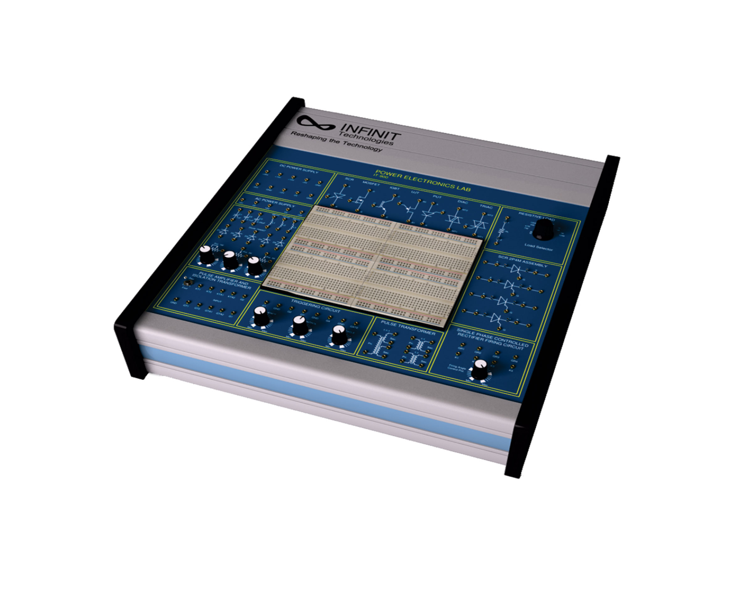
Power Electronics Training System is used to perform all the power electronics circuit experiments. It is very useful in power electronics laboratory for performing power experiments in technical colleges and universities. This trainer familiarizes student with characteristics of power electronics devices and the applications of power devices. The applications of power devices are in alarm circuit, lamp flasher, rectifiers, choppers, inverters.

Power Electronics Training System Contains Following Blocks:

DC supply, AC supply, Triggering circuit, Pulse amplifier and Isolation transformer, Pulse transformer section, Single phase controlled rectifier firing circuit, SCR assembly, Load section, Power component section.

Features:

  • Bread Board Based
  • Power Supplies Included
  • Flexibility to Perform Custom Experiments
  • TRIAC, SCR, IGBT, MOSFET, PUT and UJT Included
  • Resistors, Capacitors and Inductors Included
  • Control Circuits Included
  • P.T. and other Passive Components Included
  • Protection Circuits Included

Technical Features:

  • Fixed DC Power Supply: +5V, -5V, +12V, -12V, +15 V, +35V, -35V
  • Fixed AC Power Supply: 18V-0V-18V, 0V-15V
  • Carbon Track Potentiometer:1M, 2x5K
  • Diode: 4x1N4007
  • Capacitor: 0.33uF, 0.1uF, 1uF
  • Inductance: 10mH, 2X68mH
  • Power Devices: 5xSCR, TRIAC, DIAC, PUT, UJT, IGBT, MOSFET
  • Load Resistance Selectable: 47R/7W, 1K/1W, 1K/10W, 120ohm/5W, 2K2/2W, 270ohm/5W
  • Pulse Transformer: 2X 1:1, 1:1:1

Single Phase Controlled Rectifier Firing Circuit:

  • Firing angle control 0º – 180º

Triggering Circuit:

  • 4 Gate Signal Output
  • Frequency Range: 30Hz to 900Hz Variable
  • Amplitude: 12V
  • PWM control of G1, G2, G3 and G4
  • Duty cycle control of “Gate”
  • Signal is 0 to 100%

 Solderless Breadboard:

  • 2 Terminal Strips, Tie-point 1680
  • 4 Distribution Strips, Tie-point 400

Accessories: Power Cord, User Manual, Experiment Manual, 2mm-2mm Patch Cord