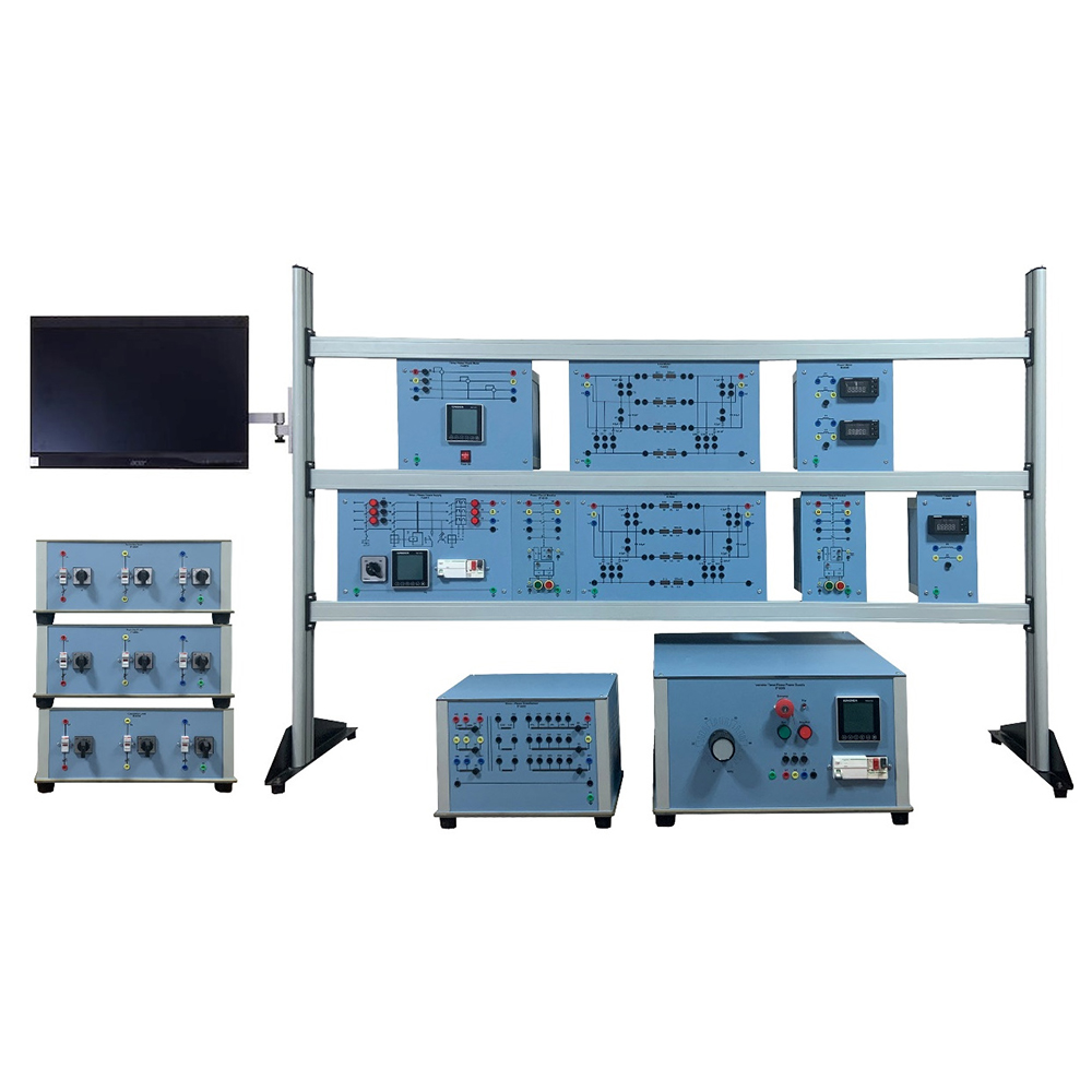
AC electrical power is generated in power stations, usually far from end users. This power is then transported over long distances using high voltage and low loss transmission lines. High voltage is achieved by using step-up transformers and is fed to the transmission lines. Similarly, at the user end, step-down transformers are used to provide power to the users. This is possible only by using transformers. Transformers are used for stepping up the voltage of the generator to values that are suitable for high voltage systems, for power exchanging between networks, for stepping down the voltages to the medium voltage level, and then for feeding the power into the low voltage network. In this laboratory, a three-phase transformer is investigated. It consists of three individual poles with different connection possibilities on the primary side and variable secondary voltage. Power transmission lines are used to transmit electrical energy from the power stations to the consumers.
The advantage of three-phase systems is that it provides the consumers with two different levels of voltage so that they can use their equipment in the best possible way. A three-phase model of an overhead power transmission line (with a simulated length of 360 km long, a simulated voltage of 380 kV, and a simulated current of 1000 A) is used, with a scale factor of 1:1000. Transmission line characteristics are investigated under various load conditions. Circuit configurations are then connected for the demonstration of various neutral point connections in three-phase mains systems. Different voltage levels are used for transmitting power; the levels are determined by the amount of power and the distance; the higher the transmission voltages, the lower the currents as well as the transmission losses. However, the network investment cost increases with the voltage.
Asymmetrical short circuits are also simulated. Other topics covered by this laboratory are reactive power compensation, the basic circuits of power engineering, series and parallel connections of operating equipment (lines, transformers), circuits involving the conversion of delta connections to star connections, circuits involving the conversion of star connections to delta connections, busbars, disconnectors, power circuit breakers, voltage, and current transformers.
List of Electrical Power Trainer
| Description | Module | Qty |
Motorized Three-Phase Power Supply
|
IT-6000M | 1 |
Line Model
|
IT-6002 | 2 |
Line Model (100 km)
|
IT-6002-1 | 1 |
Three-Phase Transformer
|
IT-6003 | 1 |
Resistive Load
|
IT-6004 | 1 |
Inductive Load
|
IT-6005 | 1 |
Capacitive Load
|
IT-6006 | 1 |
Three-Phase Power Supply
|
IT-6017 | 1 |
Power Circuit Breaker with Integrated PLC
|
IT-6019 | 4 |
Double Busbar with Two Disconnectors with Integrated PLC
|
IT-6020/2 | 1 |
Double Busbar with Four Disconnectors with Integrated PLC
|
IT-6020/4 | 1 |
Line Capacitor
|
IT-6021 | 2 |
Petersen Coil
|
IT-6022 | 1 |
Power Meter
|
IT-6048 | 2 |
Power Factor Meter
|
IT-6049 | 1 |
Three Phase Power Meter
|
IT-6051 | 2 |
| Interface Module | IT-ITM | 1 |
Base Frame
|
IT-2L | 1 |
Connecting Leads (Accessory)
|
IT-ACC | 1Set |
SCADA Software
|
IT-620S-SW | 1 |
| All in One Computer | IT-AOPC | 1 |
Expansion Module (optional):
IT-620.1
- Differential Relay (IT-6059) – 1Pc
- Three Phase Current Transformer (IT-6044) – 2Pcs
IT-620.2
- Feeder Manager Relay (IT-6058) – 1Pc
IT-620.3
- Three Phase Transformer (IT-6003) – 1Pc
Experiments with Expansion Module:
IT-620.1
- Definite time over current protection.
- Transformer differential protection.
IT-620.2
- Inverse time over current protection.
- Earth fault protection.
IT-620.3
- Paralleling of Three Phase Transformer
- Protection of parallel connected lines.


