This unit is designed to study the effect of forces in a jib crane mechanism. As suggested by the name, the two main elements of this apparatus are the jib and the tie. The jib and tie are supported on junctions on a metallic rod. The element attached at the lower end of the rod is called the jib, and the upper element is called the tie. Load is applied on both elements with use of a hanger. This is done to produce compressions and tension in the elements. The compressions and tensions causes deformation of jib and tie, and these deformations are measured using spring balance (attached to tie) and the force gauge (attached to jib). Although wall jib cranes are obsolete, the self-evident confluence of the four forces at the end of the jib illustrates the application of a triangle of forces so clearly to a real situation that this is an invaluable lesson. This wall mounted self-contained jib crane has spring balances built into its two members. After loading the member lengths can be adjusted to their no-load lengths. The jib out-hangs and the crane cable inclination can be readily changed.

Experiments
- Comparison of measured forces with a triangle of forces and theoretical values.
- Comprehension of the action of the crane cable forces on the jib and the effect of the jib inclination.
Specifications
- Determination of forces in the crane members.
- Confirmation by theory and polygon of forces.
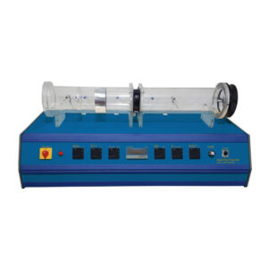
- The wall mounted crane consists of a compression jib, and a tension tie which is adjustable, and both incorporate a linear, direct reading spring balance to measure the forces in them.
- Set of weights.
- Folds flat when not in use. Jib and ties re-adjustable to the original length.
- Comprehensive technical manual.
- Set of slotted weights included.
- A load hanger applies loads through the junction of the two.