Experiments

  • Experiments on the discharge jet (diameter, velocity).
  • Determination of flow rate for various water heads.
  • Determination of flow rate coefficients.
  • Comparison between experiment and calculation Oricelli’s theorem.
  • Discharge coefficient from nozzles of varying sizes and shapes.
  • Trajectory of the water jet for various discharge velocities.
  • Effect of the height of the water column on discharge velocity.

Specification

  • Unit for investigating the discharge from nozzles, for use with the Hydraulic Bench
  • Draining of a water-filled Plexiglass cylinder through a nozzle
  • Cylinder with adjustable overflow and scale
  • 4 exchangeable nozzles
  • Tube manometer 300mmWC
  • Pitot tube to measure the differential pressure
  • Micrometer to determine the jet diameter
  • 8 tracers and white panel to record the jet trajectory
  • Maximum flow rate 22LPM
  • Determination of:
    *Coefficient of discharge (Cd)
    *Coefficient of velocity (Cv)
    *Coefficient of contraction (Cc)

Technical Data

Cylinder
Material: Plexiglas cylinder
Capacity: 10 Liter approx.
Maximum constant head: 380mm
Cylinder Height: 400mm
Cylinder Diameter: 184mm

Diameter of discharge nozzles
1x 13mm inlet with sharp edge orifice
1x 13mm cone outlet
1x 13mm cone inlet
1x 13mm rounded inlet

Scope of Delivery
1 experimental module, 4 orifices (nozzles), 8 tracers
4 magnets, 1 graph paper, 1 stopwatch

Required for Operation: Hydraulic bench (closed water
supply) or laboratory water connection

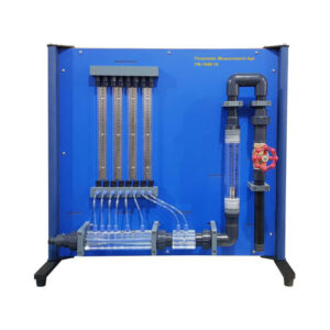
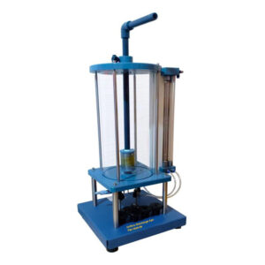
A Plexiglas cylinder is equipped with an adjustable overflow and scale which enables the height of the water column to be set and read accurately. A constant head setup, including a backboard, a series of nozzles, and a Pitot tube & micrometer, is used to illustrate vertical flow and horizontal jet paths through various orifices (nozzles).

The equipment enables students to analyze water drains vertically from a transparent supply tank through a nozzle due to the hydrostatic pressure. The velocity of the jet can be measured with a Pitot tube and a U-tube manometer. The jet diameter is measured with a micrometer.
This equipment enables students to analyze the trajectory patterns of water jets from the nozzles when they are positioned horizontally. 4 types of outlet nozzle can be compared. The trajectory of the jet can be traced using adjustable probes and recorded on a white panel.
The water supply is provided either from the laboratory mains or using the Hydraulic Bench (optional)