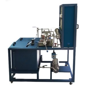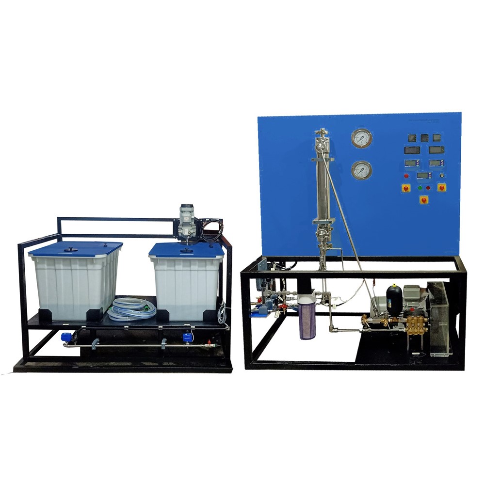
Reverse Osmosis Pilot Plant demonstrates a process when a solvent is subjected to a hydrostatic pressure larger than the osmotic pressure, reverse osmosis occurs, which is a process by which a porous membrane allows a solvent to travel through it in the opposite direction from how natural osmosis works. In a tank equipped with a stirring device, a solution of sodium chloride is mixed to a specific concentration (up to 4 % maximum). The solution is delivered to the spiral-wrapped membrane module by a pump. The pressure required for separation is created by the pump. Numerous membrane envelopes make up the spiral wound membrane module. A porous spacer sits in between two membranes to form a membrane envelope. The membrane envelope is attached to the perforated permeate collection tube on its fourth, open side. The membrane is sealed from all three sides. To guarantee the axial flow of the salt solution, additional spacers have been added between the envelopes. The membrane envelopes and spacers are spirally coiled around the permeate collection tube. At the module’s front face, the salt solution enters and moves axially between the envelopes.
The semi-permeable membrane allows water to pass through (permeate), but not dissolved sodium chloride. Water is forced through the membrane and into the envelopes by the applied pressure. The water in the envelopes exits the module axially and spirals toward the permeate collection tube. The removal of the water causes the solution to become more concentrated as it passes through the module. It returns to the raw water tank after leaving the module as retentate. A different tank is used to collect the permeate. There is an additional tank with distilled water available to flush the spiral wound membrane module. Valves enable the adjustment of flow rate and pressure. Salt concentrations in the raw water, retentate, and permeate are measured by taking the corresponding conductivity values in order to determine whether the separation was successful.