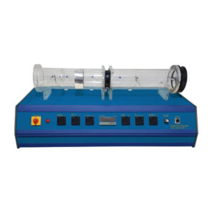
The primary function of a refrigerant is to cool down articles or substances and maintain them at a temperature lower than the ambient temperature, as heat moves from hot body to its surroundings. Using the same principle refrigerant works by removing heat from a product and transferring that heat to the outside air. The Simple Refrigerant System is a benchtop that contains components which are also used in industrial heat pump and refrigeration system. Main components of the unit are evaporator, compressor, condenser, expansion valve and refrigerant. Instrumentations are provided for the measurement of pressure & temperature. Compression refrigeration system is the name of a widely used refrigeration system. In this system, refrigerant passes through the compressor, condenser, expansion element, and evaporator, which are the four primary components. The refrigerant’s low boiling point at low pressure is used by the refrigeration system. This indicates that the low pressure side is where evaporation occurs. Heat is taken from the atmosphere and it is cooled during the refrigerant’s evaporation. After the evaporator, the condensation occurs on the high pressure side. Here, heat is released into the surrounding area. A heat pump is what you get when you utilise the released heat instead of the cooling effect. A straightforward compression refrigeration system is shown by this apparatus. Each end of the pipe coil used for the evaporator and condenser is submerged in a tank of water. The environment is simulated by the water. The expansion element is a thermostatic expansion valve. The two system pressures on the high and low-pressure sides are displayed by two pressure gauges. The evaporation temperature of the refrigerant is displayed on a separate scale. The temperature is displayed digitally using four temperature sensors. This enables calculations of the quantity of heat given to the environment (condenser, hot water) and removed from the environment (evaporator, cold water). The aggregate state of the refrigerant is shown by a sight glass upstream of the expansion valve. The lesson plan outlines the principles and offers a step-by-step walkthrough of the experiments.

Experiments
- Compression refrigeration circuit fundamentals.
- The compressor, evaporator, condenser, and expansion element are the main elements of a refrigeration system.
- The connection between a liquid’s boiling point and pressure.
- The use of a heat pump or refrigeration system.
- Gaining a fundamental knowledge of the thermodynamic cycle.
- Simple energy balance.
Specification
- Fundamentals of refrigeration in a simplified model
- Typical compression refrigeration system with piston compressor, thermostatic expansion valve, evaporator, and condenser (each in the shape of a pipe coil).
- 2 manometers with a pressure scale for the refrigerant show the values of the refrigerant on the high and low-pressure sides.
- 2 water-filled tanks with a temperature sensor to demonstrate the cooling and heating effect.
- Pressure switch to protect the compressor.
- Sight glass to monitor the aggregate state of the refrigerant
- Refrigerant R134a, CFC-free.