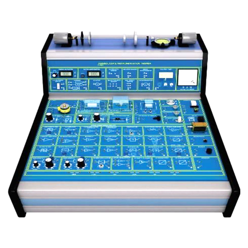
IT-5933 Trainer introduces students to input and output transducers related to speed, position and rotation, signal conditioning circuits and display devices through a wide range of practical activities. The study module includes transducers and instrumentation trainer and a curriculum manual.
Experiments:
Basic Control Systems Equipment and Terms Used
- Study the difference between open loop and closed loop systems
- Expression for the overall gain of a negative feedback closed loop system
- Calculation of overall gain of a negative feedback closed loop system from given information
- Basic components of a closed loop system and explain their functions
- Meaning of terms associated with control system equipment
Positional Resistance Transducers
- Basic construction of rotary and slider variable resistors
- State that the resistance section may be either a carbon track or wirewound
- Characteristics of output voltage against variable control setting
- Comparison of a carbon track variable resistor to the wirewound type
Display Devices
- Characteristics and application of the Timer/Counter
- Characteristics and application of the Moving Coil Meter
- Calculate the requirement to extend the voltage range of a Moving Coil Meter
- Selection of a suitable device for a particular voltage measurement
Signal Conditioning Amplifier
- Characteristics and application of DC amplifiers
- The term “Offset” and the need for offset control
- Characteristics and application of a power amplifier
- Characteristics and application of an inverter amplifier
- Characteristics and application of a differential amplifier
Mathematical Operations using OP AMPS
- Characteristics of a summing amplifier
- Characteristics of an integrator
- Characteristics of a differentiator
- Characteristics and application of a “sample and hold” circuit
Rotational Speed and Position Measurements
- Slotted Opto Transducers for Counting and Speed Measurement
- Construction, Principles and Application of a Tacho-Generator to Speed Measurement
- Characteristics of a positional control system having:
-
- Proportional
- Proportional + integral
- Proportional + derivative
- Proportional + integral + derivative control
- Characteristics of a speed control system


