The electrical power cannot be stored in large quantities and consequently, it has to be generated at the same time as the consumers needs it. The generation of electrical energy is performed by means of high power synchronous machines or alternators, whose construction design depends on the type of drive/prime movers i.e. gas, steam, water or by any motor AC/DC.
Then the synchronous generator must be connected in parallel with a constant voltage and frequency, on reaching its nominal speed, excitation voltage and current may be increased from zero until the stator voltage is brought up to the same level as that of the network.
To obtain this situation the magnitude, the phase rotation and the rotational direction of the two voltages may be achieved. This procedure is termed as synchronization.
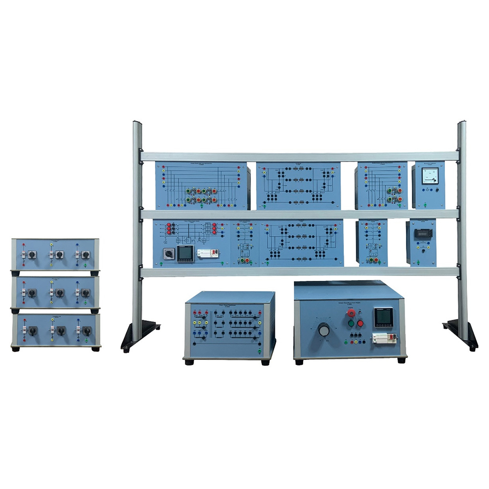
AC electrical power is generated in power stations, usually far from end users. This power is then transported over long distances using high voltage and low loss transmission lines. High voltage is achieved by using step up transformers and is fed to the transmission lines. Similarly, at user end, step down transformers are used to provide power to the users. This is possible only by using transformers. Transformers are used for stepping up the voltage of the generator to values which are suitable for high voltage systems, for power exchanging between networks, for stepping down the voltages to the medium voltage level and then for feeding the power into the low voltage network. In this laboratory a three-phase transformer is investigated. It consists of three individual poles with different connection possibilities on the primary side and variable secondary voltage. Power transmission lines are used to transmit electrical energy from the power stations to the consumers.
Advantage of three-phase systems is that it provides the consumers with two different levels of voltage, so that they can use their equipment in the best possible way. A three-phase model of an overhead power transmission line (with a simulated length of 360 km long, a simulated voltage of 380 kV and a simulated current of 1000 A) is used, with a scale factor of 1:1000. Transmission line characteristics are investigated under various load conditions. Circuit configurations are then connected for the demonstration of various neutral point connections in three-phase mains systems. Different voltage levels are used for transmitting power; the levels are determined by the amount of power and the distance; the higher the transmission voltages, the lower the currents as well as the transmission losses. However the network investment cost increases with the voltage.
Asymmetrical short-circuits are also simulated. Other topics covered by this laboratory are reactive power compensation, the basic circuits of power engineering, series and parallel connections of operating equipment (lines, transformers), circuit involving the conversion of delta connections to star connections, circuit involving the conversion of star connections to delta connections, busbars, disconnectors, power circuit breakers, voltage and current transformers.
In an Electrical Power System currents and voltages must be monitored constantly to make sure that the values remain within the required limits. This will also switch off the faulty sections from the main supply network. It is important to identify the fault and to isolate the faulty section automatically from the network because this will result in collapse of the entire electrical power system. These protection systems need to be fast and reliable in events of fault in order to avoid any large scale damage. It is important that the protection system identifies and isolates the faulty section without affecting the remaining power system.
A number of protective relays are analyzed: under/over voltage time relays, definite time over-current relays, inverse time over-current relays, combined over-current and earth-fault relay, directional relay and earth-fault relays. Large energy consumers like industrial plants, processing plants and manufacturing units are required to provide compensation for reactive power used by them. Modern electrical control circuits also generate harmonics in the network.
This laboratory addresses the topics like reactive power compensation, reactive power controllers, measurement of electrical energy in three phase networks, cost of power consumed by the customers. These topics are analyzed from the theoretical point of view and also by means of practical examples.
List of Electrical Power Trainer
| Description | Module | Qty |
Variable Three-Phase Power Supply
|
IT-6000 | 1 |
Variable DC Power Supply
|
IT-6001 | 1 |
Line Model (360 km)
|
IT-6002 | 2 |
Line Model (100 km)
|
IT-6002-1 | 1 |
Three-Phase Transformer
|
IT-6003 | 1 |
Resistive Load
|
IT-6004 | 1 |
Inductive Load
|
IT-6005 | 1 |
Capacitive Load
|
IT-6006 | 1 |
DC Motor
|
IT-6007 | 1 |
Three-Phase Synchronous Machine
|
IT-6008 | 1 |
Three-Phase Squirrel Cage
|
IT-6009 | 1 |
Magnetic Brake
|
IT-6010 | 1 |
Brake Control Unit
|
IT-6011 | 1 |
| Load Cell | IT-6012 | 1 |
Speed Sensor
|
IT-6013 | 2 |
Universal Base
|
IT-6014 | 2 |
Digital Tachometer
|
IT-6015 | 1 |
| Experiment Transformer (0-250 V @ 5 A)
Outputs:
|
IT-6016 | 1 |
Three-Phase Power Supply
|
IT-6017 | 1 |
DC Variable Power Supply
|
IT-6018 | 1 |
Power Circuit Breaker with Integrated PLC
|
IT-6019 | 4 |
Double Busbar with Two Disconnectors with Integrated PLC
|
IT-6020/2 | 1 |
Double Busbar with Four Disconnectors with Integrated PLC
|
IT-6020/4 | 1 |
Line Capacitor
|
IT-6021 | 2 |
Petersen Coil
|
IT-6022 | 1 |
CT Load
|
IT-6023 | 1 |
VT Load
|
IT-6024 | 1 |
L/C Loads
|
IT-6030 | 1 |
Reactive Power Controller
|
IT-6032 | 1 |
| Switchable Capacitor Battery
Switchable Capacitor Banks for Reactive Power Compensation. In star connection with discharging resistors:
|
IT-6033 | 1 |
Moving Coil Ammeter (1000mA)
|
IT-6034 | 4 |
Moving Coil Ammeter (3A)
|
IT-6035 | 3 |
Moving Iron Ammeter (5A)
|
IT-6036 | 2 |
Moving Iron Voltmeter (600V)
|
IT-6037 | 2 |
Moving Iron Voltmeter (500V)
|
IT-6038 | 4 |
Synchronization Indicator
|
IT-6039 | 1 |
Phase Sequence Indicator
|
IT-6040 | 1 |
Double Frequency Meter (45-65Hz)
|
IT-6041 | 1 |
Double Voltmeter (500V)
|
IT-6042 | 1 |
Single-Phase Current Transformer
|
IT-6043 | 1 |
Three-Phase Current Transformer
|
IT-6044 | 1 |
Single-Phase Voltage Transformer
|
IT-6045 | 1 |
Three-Phase Voltage Transformer
|
IT-6046 | 1 |
Summation Current Transformer
|
IT-6047 | 1 |
Power Meter
|
IT-6048 | 1 |
Power Factor Meter
|
IT-6049 | 1 |
Three-Phase kWH / kVArh Meter
|
IT-6050 | 1 |
Three-Phase Power Meter
|
IT-6051 | 1 |
Synchronoscope
|
IT-6053 | 1 |
Moving Coil Ammeter (1000mA)
|
IT-6054 | 1 |
Moving Coil Voltmeter (30V)
|
IT-6055 | 1 |
Feeder Manager Relay
|
IT-6058 | 1 |
Electronics Stop Clock
|
IT-Clock | 1 |
Base Frame
|
IT-2L | 4 |
Leads (Accessory)
|
IT-ACC | 1set |
Expansion Module (optional):
- Differential Transformer Relay – IT-6059 – 1Pc
- Three Phase Current Transformer – IT-6044 – 2pc
Experiments with Expansion Module:
- Definite time over current protection.
- Inverse time over current protection.
- Earth fault
- Transformer differential protection.


