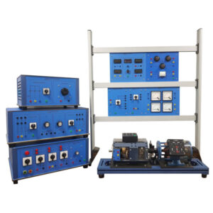
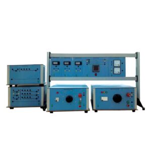
The electrical power cannot be stored in large quantities and consequently, it has to be generated at the same time as the consumers needs it. The generation of electrical energy is performed by means of high power synchronous machines or alternators, whose construction design depends on the type of drive/prime movers i.e. gas, steam, water or by any motor AC/DC.
Then the synchronous generator must be connected in parallel with a constant voltage and frequency, on reaching its nominal speed, excitation voltage and current may be increased from zero until the stator voltage is brought up to the same level as that of the network.
To obtain this situation the magnitude, the phase rotation and the rotational direction of the two voltages may be achieved. This procedure is termed as synchronization.
List of Electrical Power Trainer
| Description |
Module |
Qty |
Variable DC Power Supply
- Key Operated Emergency Switch
- Protection: 10 A, Direct On Line (DOL) Starter
- Push-Button: Start, Stop and Emergency
- Motor Protection Breaker: 10 A
- Digital DC Ammeter
- Digital DC Voltmeter
- Output Adjusted by Rotary Knob
- Output: 0-250V @ 8A
- Supply voltage: Single-Phase from Mains
|
IT-6001 |
1 |
Resistive Load
- Max Load in 3-Phase: 1200 W
- Rated voltage: 380/220V
- Connection Type: Y/
- Rated voltage in single-phase: 220 V
|
IT-6004 |
1 |
Inductive Load
- Max Reactive Power: 890 Var
- Rated voltage: 380/220 V
- Connection Type: Y/
- Rated voltage in single-phase: 220 V
|
IT-6005 |
1 |
Capacitive Load
- Max Reactive Power: 1090 Var
- Rated voltage: 380/220 V
- Connection Type: Y/
- Rated voltage in single-phase: 220 V
|
IT-6006 |
1 |
DC Motor
- Power: 2.2 kW
- Voltage: 220 VDC
- Speed: 3600 rpm
- Current: 13A
|
IT-6007 |
1 |
Three-Phase Synchronous Machine
- Alternator: 1.1 kVA
- Motor: 1 kW
- Voltage: 220/400 V / Y
- Current: 4/2.5 A
- Speed: 3000 rpm
- DC rotor excitation winding
|
IT-6008 |
1 |
Speed Sensor
- For measuring the rotation speed. Suitable for being mounted on the machines of the laboratory.
|
IT-6013 |
1 |
Universal Base
- Alloy structure mounted on anti-vibration rubber feet, provided with slide guides for fixing one or two machines. Complete with coupling guard.
|
IT-6014 |
1 |
Digital Tachometer
- Supply: Single Phase from the mains
- Range: 0 to 9999 rpm with signals coming from the standard optical transducers
- Signal Input: Optical Transducer
|
IT-6015 |
1 |
| Experiment Transformer (0-250 V @ 5 A)
Outputs:
- Single-Phase: 0-250 V @ 3 A
- Protection: 10A Breaker, Fuse 2.5A and Fuse 5A
- Low voltage Single Phase:
- 0-42 V @ 3 A
- 0-24 V @ 6A
- 0-12 V @ 12 A
- DC Voltage: 50 A Rectifier for all ranges
|
IT-6016 |
1 |
Three-Phase Power Supply
- Digital 3-phase analyzer
- Input: 3-Phase 380V
- Output Protection: 30 A current operated earth leakage circuit breaker
- Four-pole motor protection switch: 6.3-12 A.
- Three-phase indicator lamps
- Output through 5 safety terminals: L1, L2, L3, N and PE
|
IT-6017 |
1 |
| DC Variable Power Supply
|
IT-6018 |
1 |
Power Circuit Breaker with Integrated PLC
- PLC integrated inside
- Contact Load: 400 VAC @ 3 A
- Supply Voltage: Single-Phase from the mains
|
IT-6019 |
1 |
| Moving Coil Ammeter (1000mA)
|
IT-6034 |
2 |
| Moving Coil Ammeter (3A)
|
IT-6035 |
2 |
| Moving Iron Voltmeter (600V)
|
IT-6037 |
1 |
Synchronization Indicator
- 3 series of 2 lamps
- Voltage: 380 V
- H11 – H12, H21 – H22 and H31 – H32
|
IT-6039 |
1 |
Phase Sequence Indicator
- Operating voltage: 250-500V
- Frequency: 45Hz – 65 Hz
|
IT-6040 |
1 |
Double Frequency Meter (45-65Hz)
- Range: 2 x (45-65) Hz
- Voltage: 380 V
|
IT-6041 |
1 |
| Double Voltmeter (500V)
|
IT-6042 |
1 |
Power Meter
- Measurement: Voltage, Current, Frequency, Active Power, Reactive Power and Power Factor
- Supply: Single Phase from the mains
- Display: 7-Segment LED
- Measurement ranges:
- Volt: 0-600V
- Current: 5/1A via CT
- Frequency ranges:
- Active Power: 50/60 Hz
- Reactive Power: 50/60 Hz
|
IT-6048 |
1 |
Power Factor Meter
- Measurement: Voltage, Current, Frequency, Active Power, Reactive Power and Power Factor
- Supply: Single Phase from the mains
- Display: 7-Segment LED
- Measurement ranges:
- Volt: 0-600V
- Current: 5/1A via CT
- Frequency ranges:
- Active Power: 50/60 Hz
- Reactive Power: 50/60 Hz
|
IT-6049 |
1 |
Synchronoscope
- Voltage: 380 V
- Frequency: 45-60 Hz
|
IT-6053 |
1 |
| Moving Coil Ammeter (1000mA)
|
IT-6054 |
1 |
| Moving Coil Voltmeter (30V)
|
IT-6055 |
1 |
| Base Frame
|
IT-2L |
1 |
| Leads (Accessory)
|
IT-ACC |
1set |
Expansion Modules (optional):
IT-620.1
- Differential Relay (IT-6059 ) : 1pc
- Three Phase Current Transformer (IT-6044) : 2pcs
IT-620.2
- Feeder Manager Relay (IT-6058) : 1pc
IT-620.3
- Three Phase Transformer (IT-6003) : 1pc
Experiments with Expansion Modules:
IT-620.1
- Definite time over current protection.
- Transformer differential protection.
IT-620.2
- Inverse time over current protection.
- Earth fault protection.
- Protection of parallel connected lines.
IT-620.3
- Paralleling of Three Phase Transformer


