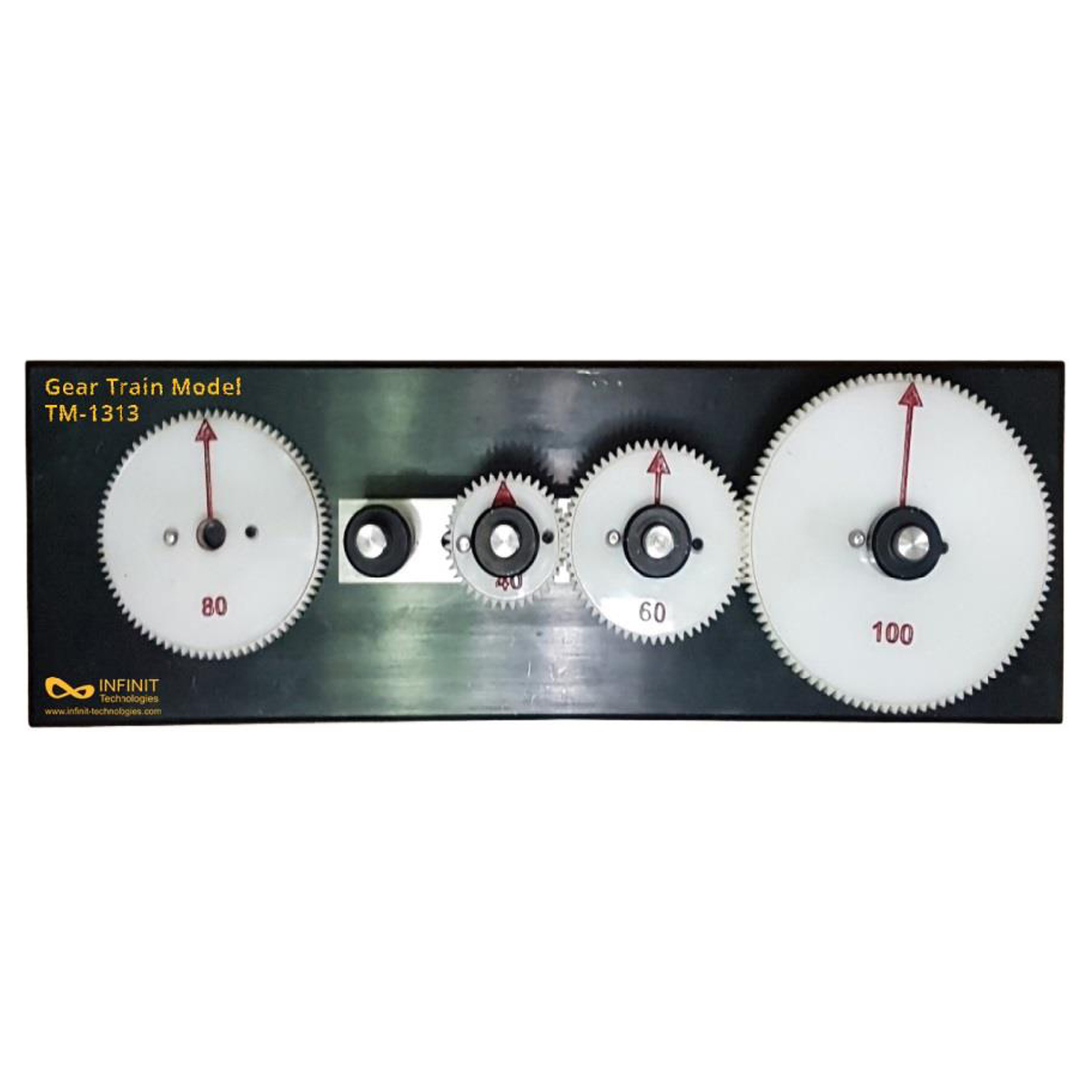
This apparatus is designed to demonstrate the mechanism of compound gears. Through this apparatus students can inspect and calculate the changes in gear ratio, velocity ratio and torque ratio due to intermediate gears in compound gearing. In this apparatus gear of different pitch circle diameter and number of teeth are meshed together and seated on base at same level. Pins are used to lock them and these gears are adjustable. These gears are adjustable and students can perform different experiments through changing the position of the gears, and different velocity ratio and torque ratio can be achieved. This apparatus is used to demonstrate belt drives, wheel and disk drives, and gear trains. Basic terminology and relationships, e.g. the transmission ratio, direction of rotation reversal, reference circle and modulus, the function of intermediate gears, and soon can be clearly demonstrated. A solid frame made of anodised aluminium section forms the base for the unit. The bearings for the pulleys and gears are attached to the T-slots in the profile using clamping Screw. These are easy to release and can be slid horizontally making a wide range of different set-ups possible. All experiments are carried out using manual power. The size of the unit ensures that the experiment is clearly visible even for larger groups of students.
Experiments
- Function and differences between belt drives, wheel a n d disc drives and gear trains.
- Explanation and demonstration of:
- Transmission
- Reference circle
- Modulus
- Function of intermediate gears
- Compound Gear Functionalities
Specifications
- Demonstration experiment on the how gear trains work
- Steel gears
- Base frame made of aluminum section, anodized


