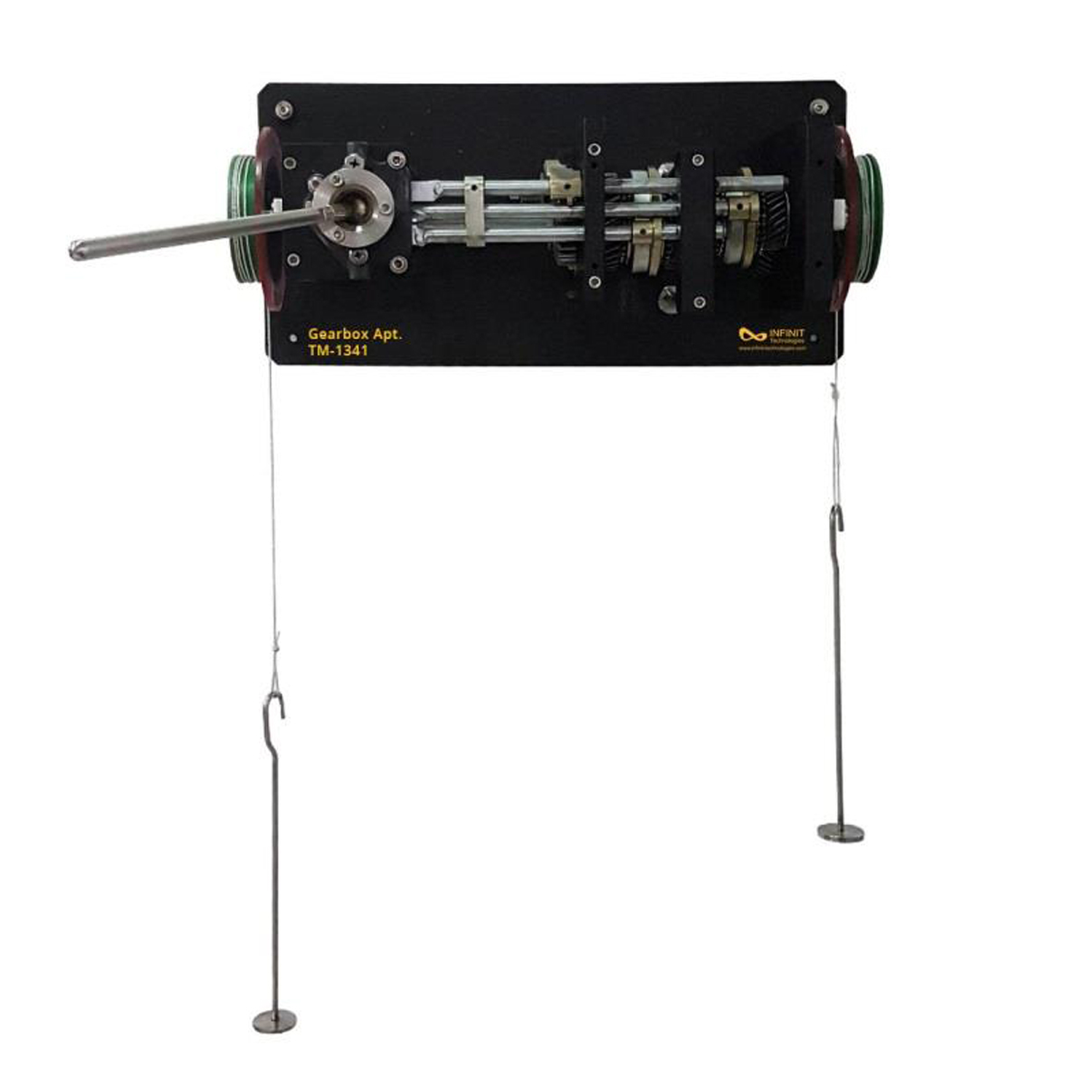
Gearbox Apparatus A sturdy wall mounted frame houses all the gears, shafts, bearings and levers contained within this apparatus. A ‘H’ style change with gear change lever and knob allows the use of the different gears within the system. All gears run on shafts fitted into bearings and the changing mechanism ensures smooth transition. The gears are industry standard gears finished in high quality and mesh together in different ratios within the frame. Gears can be slid across each other by the use of a lever with ball knob and the whole gearbox can be rotated using the rotating handle attached on the side of the input pulley. Protractors on the input and output shaft pulleys are fitted. This unit is hand operated. A set of clear, transparent guards are fitted so that safety is maintained and clear visibility is ensured. A set of masses and hangers is supplied to allow the shafts to be driven. The input and output pulleys allow loads to be applied for lifting and lowering. A comprehensive instruction manual for lecturer and student, giving full details on apparatus assembly and operation as well as example results. All necessary assembly and operational tools are provided.
Experiments
- Measure of the angular displacement at the input and output of the gear box and comparison with the calculated values.
- Calculation of the efficiency for different ratios according to the torque at entry.
- Enables velocity and torque ratios to be determined.
Specification
- ‘H’ selection of gears.
- Module 1 gears.
- 20tooth, 26tooth, 52tooth, 39tooth gears in system.
- Three (3) forward gears and one(1) reverse.
- Pulley diameter Ø87.5mm.
- Input and Output shaft can be reversed.
- Two (2) hangers of 100g each.
- Set of slotted weights.
- Comprehensive instruction manual provided.
Scope of Delivery
- 1 experimental unit
- 1 instruction manual
- 2 sets of weights
- 1 thread


