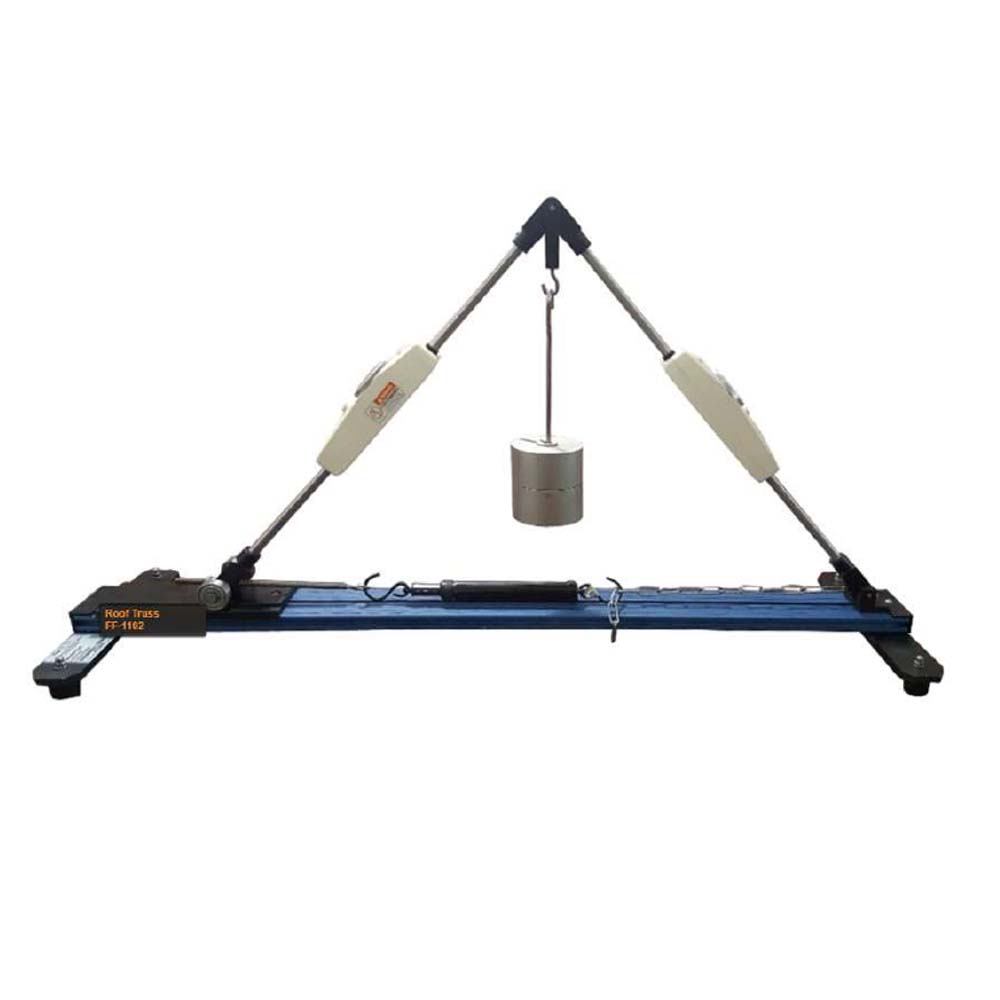
The apparatus shown is a simple roof truss bar structure. This apparatus is used in measuring the deformation of various elements of roof truss. In this single plane system the bars are only subjected to tension and compression. This is because loads are applied only at the nodes. When load is applied to roof truss, its members undergo strain. The unit shown consists consists of a base structure, two metallic elements and one adjustable element with a spring balance and a chain attached to it. The base structure provides support locations for the roof truss and the metallic elements and adjustable element are arranged to form a roof truss in a triangular shape. The three members (elements) are joined together using pin joints in a manner in which pin joints are free to move. Two of the pin joints also form the supports (fixed and free with bearings) and are clamped to the sturdy aluminium section base frame. The external load is applied to the upper pin joint by means of weights. The bar forces occurring are measured directly on force gauge in the middle of the bar. The method of joints enables the bar forces to be determined by formulating a system of equations. The structure of apparatus can also be constructed at different angles as a longitudinally adjustable chain is also installed in the apparatus. Each member also has force gauge to find out the individual force on each member due to the applied load.
Experiments
- Measurement of bar forces (ties and Rafter).
- Calculation of bar forces by the method of joints.
- Comparison: measurement result-calculation-graphical method.
Specifications
- Resolution of forces in a single plane, statically determinate system.
- 3 pin joints, 2 of which serving as supports one fixed and one free longitudinal.
- 2 bars each fitted with a force gauge (compression) and one member fitted with spring balance (tension).
- 3 element and force markers.
- 2 rafters with compression gauges and fixed length, 1tie with variable length.
- Different angles adjustable between bars.


