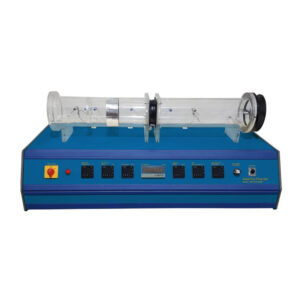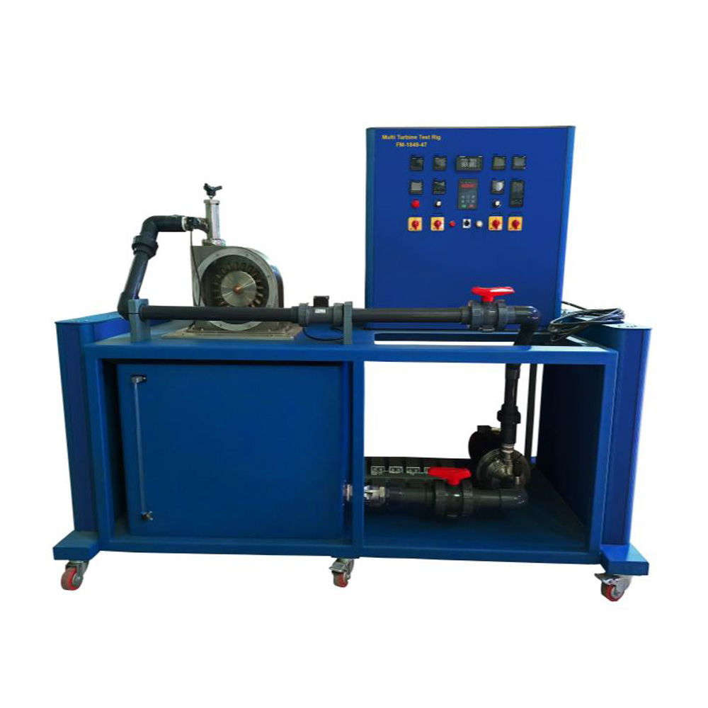
The Multi Turbine Test Rig is designed to be a self-contained unit to demonstrate the operation and performance characteristics of three types of turbines, namely Francis (radial flow) turbine, Kaplan (axial) turbine, and Pelton (impulse) turbine. The turbines will be driven by a 2.2kW pump and come complete with dynamometer. The Multi Turbine Test Rig is capable of performing experiments on mechanical power out, hydraulic power in, hydraulic efficiency, and specific speed. The Multi Turbine Test Rig consists of a centrifugal pump with controlled motor speed, three interchangeable sets of Pelton, Francis, and Kaplan turbine complete with individual casing respectively. The test set is a self-contained unit comprising two main assemblies; an instrument / control console and a welded steel base frame, which carries the pump, turbine set, and water reservoir tank. In terms of the functionality, an inverter with speed dial controls the centrifugal pump motor speed in between 0 to approximately 3000 rpm. Power transducer is provided to measure the power consumption of the pump motor. Speed sensor is installed on DC generator shaft to measure the rotational speed of the turbine, as DC generator is directly coupled with turbine. Load cell is attached on DC generator for torque measurement. The torque arm is directly depressing against the load cell arm, there by tensioning against the motion. With the aid of the load sensor, we can detect
the torque or force acting on the turbine. A volt meter and an ampere meter are provided to measure volt and current generated by the DC generator. Analogue manometers are installed on each inlet and outlet of turbine set to measure the
pressure on the respective locations. Electrical resistive load (lamps) are installed to provide necessary load to the DC generator during experiment.
Process Flow
Water is pumped by the centrifugal pump from the reservoir tank into the turbine casing and spins the turbine as well as DC generator motor. This will generate power and displayed as voltage and current on the control panel.
The water will be re-circulated. The pump motor speed could be varied to perform studies on the turbines with different head and flows