When laying pipes, it is essential that they are adapted to the circumstances of their environment, which means the pipes will necessarily include deflections in the form of bends. Changing the direction of flow in a pipe changes the pressure conditions. The pressure curve during a change in the flow direction is investigated using the example of a 90° pipe bend.
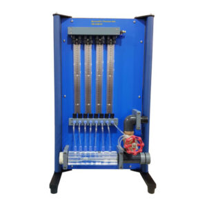
This experimental unit, when used in the aerodynamics trainer FM-1849-56, allows the measurement of the static pressure at 29 pressure measuring points along the pipe bend. The transparent pipe bend has a constant rectangular cross-section with ten pressure measuring points each on the top and bottom. Pressure measuring points are located in the region of the curvature on both sides: four on the left side and five on the right side. The pressure measuring points are connected to the tube manometers in FM-1849-56 via the hoses supplied. The
static pressures can be read on the tube manometers. To illustrate the pressure distribution, the static pressure at a measuring point is related to the maximum pressure. The graphical representation of the pressure curve shows a low pressure along the inner radius and an overpressure along the
outer radius.
The experimental unit is attached to the FM-1849-56 trainer, simply and precisely with quick release fasteners.

Experiments
- Investigation of the pressure curve at a 90° pipe bend
- Determination of the static pressure at 29 pressure measuring points
- Representation of the pressure distribution
Specification
- Determining the pressure conditions in flow through a pipe bend
- Measurement of static pressure at 29 pressure measuring points along the bend
- 29 pressure measuring points: 4 on the left side and 5 on the right side, 10 on the top side and 10 on the bottom side
- Accessory for aerodynamics trainer FM-1849-56
- 16 tube manometers of FM-1849-56 for displaying the pressures