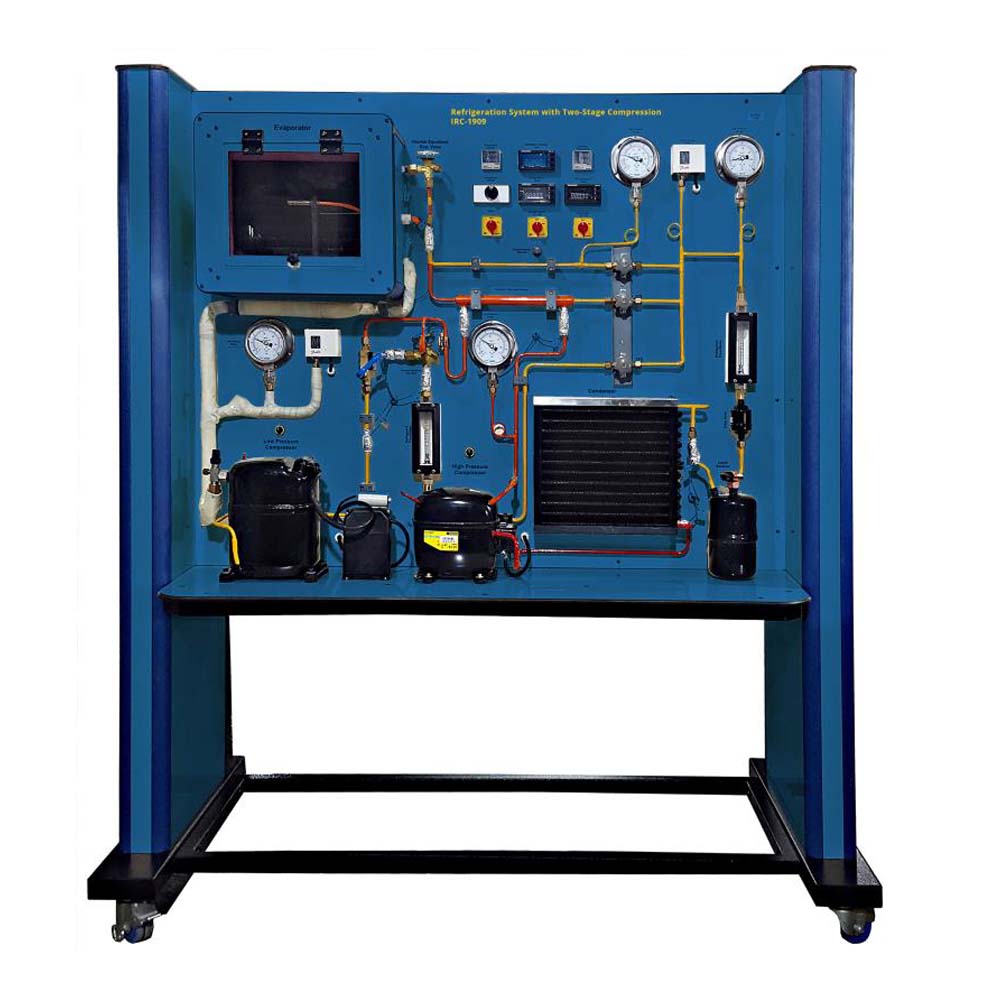
Refrigeration systems with two-stage compression are used for the generation of particularly low temperatures. Large pressure differences between the evaporator and condenser are necessary at very low temperatures. At high pressure ratios, a compressor’s volumetric efficiency drastically decreases. As a result, two compressors are linked together in series, each of which has a low pressure ratio. As a result, the low pressure stage compressor can be sized more advantageously. Because of the huge specific volume, a higher capacity at a lower drive power is needed. Additionally, intercooling between the low pressure and high pressure compressors (LP and HP) increases compression efficiency by bringing the HP compressor’s outlet temperature down to safe levels. The IRC-1909 equipment employs injection intercooling. The receiver injects a small quantity of liquid refrigerant into the LP compressor’s outlet line. By evaporating, the liquid refrigerant cools the intake gas for the HP compressor. The super cooling of the liquid refrigerant can be increased upstream of the expansion valve using an add-on heat exchanger in the injection cooler. As a result, the evaporator’s capacity can be increased. Valves make it possible to turn off the heat exchanger for refrigerant super cooling or the injection intercooling. This can show how they have an impact on the system. Sensors record and display all relevant measured values. Real-time analysis and representation of the process in the p-h diagram are made possible by the simultaneous transmission of the measurements to the programme (optional). Two flow metres also display the volumetric flow rates for the intercooling and the total volumetric flow rate.
Software IRC-1909SW (optional)
DAQ software specially designed in National Instrument™, LABVIEW™ environment to measure and calculate the results of apparatus. The software is optional and while using software a set of electronic sensors are included. The software can be run with any Windows™ environment


