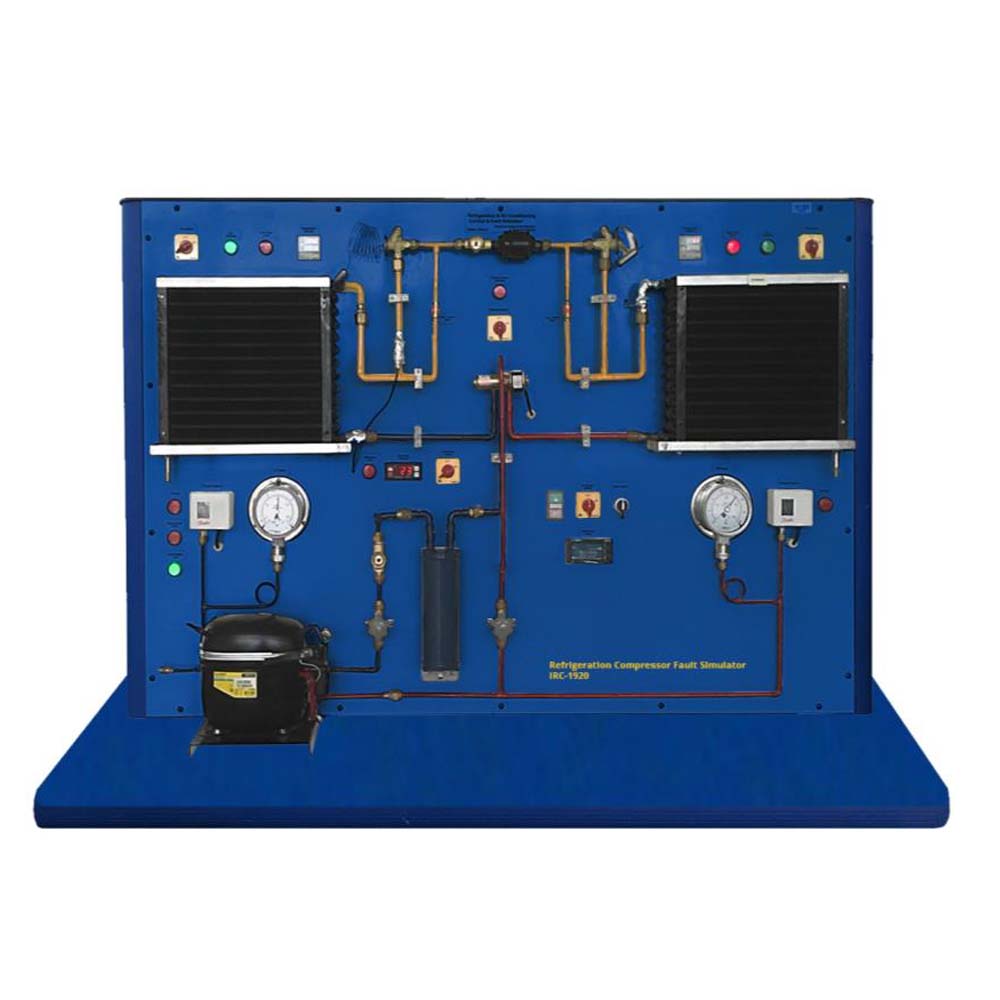
A thorough understanding of the design and operation of the various electrical components as well as the ability to read circuit diagrams is necessary to detect electrical issues in refrigeration systems. Students are assisted by this trainer in learning this information. The electrical parts needed to start and run a refrigerant compressor are already wired and are easily visible on a panel. The necessary start-up relay and capacitor for the motor are examined. Circuit breakers and other common protection devices are also organized in an easily visible manner. It is possible to simulate various faults, such as a motor coil fracture, a short circuit in the operational capacitor, or welded contacts in the start-up relay (compressor faults). Voltages and resistances can be tested using the multimeter for defect indication (not Providing).
Software IRC-1920SW (optional)
DAQ software specially designed in National Instrument™, LABVIEW™ environment to measure and calculate the results of apparatus. The software is optional and while using software a set of electronic sensors are included. Software can be run with any Windows™ environment.


