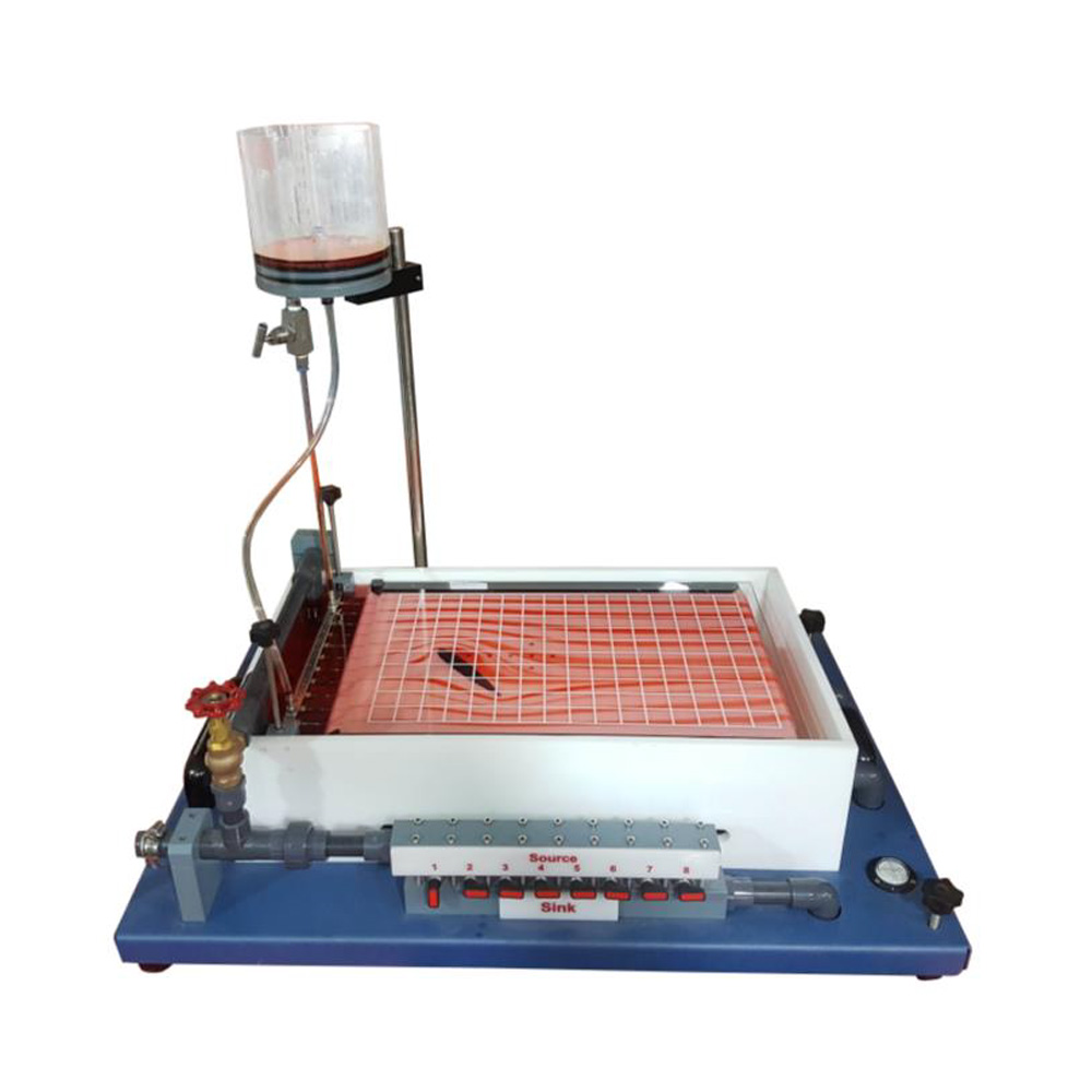
The laminar, two-dimensional flow in this apparatus is a good approximation of the flow of ideal fluids: the potential flow. All physical systems described with the Laplace equation can be demonstrated with potential flow. This includes current and thermal flows as well as magnetic flux. The main part of the apparatus is a classic Hele-Shaw cell with additional water connections for sources and sinks. The laminar, two-dimensional flow is achieved by water flowing at low velocity in a narrow gap between two parallel glass and acrylic plates. The parallel flow generated in this way is non-vortical and can be regarded as potential flow. Sources and sinks are generated via eight water connections between the plates. The flow lines are displayed on the glass plate by injecting a contrast medium (ink) via twelve injecting points. In experiments the flow around bodies is demonstrated by inserting models into the parallel flow. Interchangeable models such as a cylinder, guide vane profile or nozzle contour are included. To model the flow without models, it is possible to overlay parallel flow, sources, sinks and dipoles as required. This allows the demonstration of the formation of Rankine half-bodies. The water flow rate and the quantity of contrast medium injected can be adjusted by using valves. The water connections are also activated by valves and can be combined as required.
Experiments
- Visualization of streamlines in
- flow around drag bodies: cylinder, guide vane profile, square, rectangle
- flow through models: nozzle contour, sudden contraction or enlargement
- flow separation, flow with 90° deflection
- Visualization of streamlines in
- flow around drag bodies: cylinder, guide vane profile, square, Rectangle
- flow through models: nozzle contour, sudden contraction or enlargement
- flow separation, flow with 90° deflection
- Modelling the flow around bodies by overlaying parallel flow and sources and/or sinks
- formation of Rankine half-bodies
- demonstration of a dipole
- Analogy between potential flow and other physical systems which are described by the Laplace equation
Specification
- Demonstration of potential flow in a Hele-Shaw cell for visualising flow lines.
- Flow around models: cylinder, square, rectangle, guide vane profile, various models for changes in cross-section.
- Modelling the flow around contours without models by overlaying parallel flow with sources or sinks.
- Water as flowing medium and ink as contrast medium.
- Hele-Shaw cell made of two glass plates arranged in parallel with narrow gap.
- Upper glass plate, hinged for swapping models.
- Bottom plate with cross-shaped water connections for generating sources/sinks, can be combined as required.
- Grid in the panel for optimal observation of the streamlines.
- Flow velocity, water inlet and water outlet in sources/sinks as well as dosage of the contrast medium can be adjusted by using valves.


