Experiments

Investigation of pressure losses in bends, branches, changes of section and over straight lengths of duct, together with the variation in pressure drop with velocity.

Determination of the ‘K’ factor for the pressure loss of the above components in each particular configuration.

Examination of typical components, fabrication, installation and assembly techniques used in air handling systems.

Investigation of the fan pressure and volume flow characteristics at various supply voltages.

Examination of standard types of panel and bag filters and their pressure drop against face velocity.

Carrying out commissioning leak testing on all components in an installed system.

Adding tee branch and two diffusers in a system and investigating their effect

Measurement of air flow rate using pitot-static traverse, orifice pressure differential and anemometer methods.

Balancing of air flow distribution in a series or two branch parallel distribution system using either main damper or fan speed flow control.

Specification

Fan Unit: Motor power 0.75kW (approx.) on load.

Starting load is greater.

Fan supply pressure of up to 890Pa, flow rate of up to 0.8m3/s depending upon the blockage factor.

Fan discharge directly into a 200mm dia. Galvanized steel duct.

Ductwork Galvanized steel.

A combined vertical (Range 0~2000 Pa) and inclined (Range 0~200 Pa) manometer.

Unit supplied with pitot static tube.

A battery powered rotating vane anemometer with digital readout. Range approximately 0~30m/s.

All rotating components covered when filter and holder are in position.

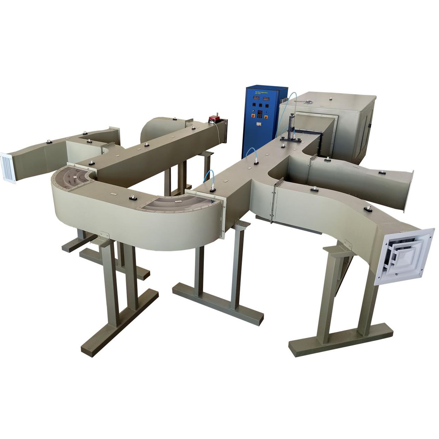
A realistically scaled ventilation training unit that enables students to learn about both fundamental fluid mechanics and airflow as well as the more complex process of commissioning and balancing a multi-ducted air distribution system.  A rectangular air inlet and filter holder are also included in the unit, along with a forward-curving variable speed centrifugal fan and integral control console. According to the blockage factor, the fan’s feed pressure can reach 890Pa and its flow rate can reach 0.8m3/s. A 200mm dia. galvanized steel duct that the fan discharges into is directly connected to the distribution ductwork. The equipment comes with enough parts to allow users to conduct parallel branch and line balancing tests.  There are at least 6 air supply locations that can be balanced on the constructed unit to provide a variety of airflows. A variety of studies can be carried out using a portable manometer, pitot static tube, and hand-held anemometer.

Software IRC-1921SW (optional)

DAQ software specially designed in National Instrument™, LABVIEW™ environment to measure and calculate the results of apparatus. The software is optional and while using software a set of electronic sensors are included.  Software can be run with any Windows™ environment.