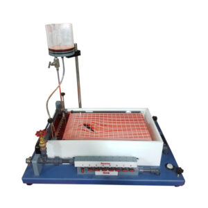
A bending moment that acts on a plane inclined to the major axis may be applied to a member. Unsymmetrical bending is the term for this kind of bending, which does not take place in the cross-symmetry section’s plane. The issue with flexure in general might be referred to as skew bending because it is distinct from symmetrical bending. A horizontal cantilever makes up the Unsymmetrical Cantilever Apparatus. At its lower end, the primary column is firmly secured to a rigid framework. Beams from various sections may be used. At the top of the column, a loading head can freely rotate at various angles around the vertical axis of the beam. By using a lever fastened to the beam fixed on the spinning head, a vertical weight may be applied to the free end of the beam. Two dial gauges mounted on the head perpendicular to each other are used to measure the deflections of the beam. Four steel beams are provided, one with a rectangular section, the other with an L-shaped section, the third with a U-shaped section, and the fourth with an I-shaped section. The beam specimens are arranged on this table unit so that the experimental set-up may be observed clearly. The beam’s bending can clearly be observed by looking at it from the front. The angular position is marked on a graded disc, and the interchangeable beams of rectangle-shaped, U-shaped, L-shaped, and I-shaped section are clamped at one end in a solid support. Using a set of weights, a point load is imparted to the free end. To provide a combined torsion/bending load, the locating bolts enable a 25mm offset on either side of the application of force. To investigate the shear centre, this is required. Dial gauges count the amount that the beam’s end has deflected. Precise zeroing is possible using adjustment bolts.

Experiments:
- Straight bending of a beam of I cross-section.
- Unsymmetrical bending of a beam of L cross – section.
- Torsion moment and shear centre on a beam of U cross-section.
- Torsion moment and shear centre on a beam of rectanguler cross-section.
Specifications:
- Table-top experiment for general and unsymmetrical bending of straight beams.
- Eccentricity of load application point adjustable
- Four beams of I, L, U and rectanguler cross-section