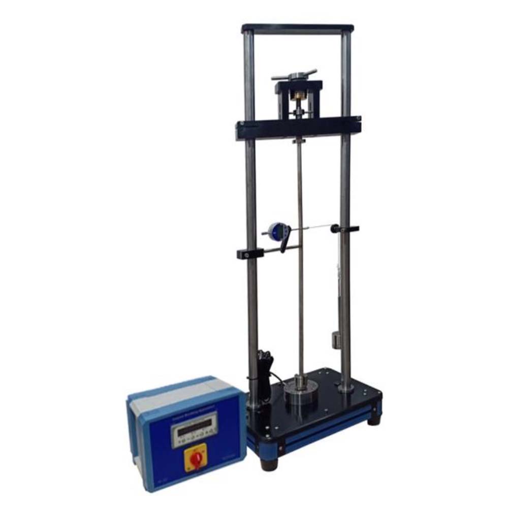
Studying buckling on struts under varied end conditions is done using the bench top equipment. The failure related to instability, known as buckling, in a body subject to compressive load is sometimes overlooked. Two vertical columns make up the Column Buckling Apparatus, which applies load using a screw via a sliding guide in a ball bushing. The built-in support is a cylinder in a socket, and the pivot support is a wedge on a V-notch. A load cell and a dial gauge are used to measure the load on the strut and deflection, respectively. A weight hanger and weights are used for side loading. The loading beam’s height can be adjusted to accommodate various strut lengths. The term “buckling” refers to the lack of stability in technical mechanics. The axis of the bar deflects laterally under the influence of compressive forces and under increasing load until it abruptly and violently fails (collapses), even before the fracture point is reached. During this process, the stresses in the bar frequently stay inside the elastic range.Column Investigating the buckling behaviour of bars under various conditions is called buckling. Experiments are used to demonstrate all pertinent buckling issues. Depending on the buckling instance, one end of a bar is either fastened or pinned for the purpose. Compressive force is applied to the bar using a hand-operated spindle and a load-carrying cross-arm with height adjustment. The test bar is shielded from torsional loading by an axial bearing located between the spindle and the bar support. The applied force is measured by a hydraulic load cell, which displays the information on a pressure gauge. A dial gauge displays the bar’s lateral deflection. Experiments demonstrate a variety of influences, including bar lengths, materials, and support mechanisms. On the test bar, extra shear forces can be produced using a transverse load application mechanism. Both vertical and horizontal operation are possible with the experimental unit. To adjust to the selected choice, the load gauge can be turned 90 degrees. The range of experiments made possible by the apparatus is increased by a supplemental set. The many components of the experiment are organised neatly and kept safe in a storage system..
Experiments:
- Investigation of buckling behaviour under the influence of
* various methods of support
* various bar lengths
* various materials - Verification of the Euler Theory: Buckling on elastic bars.
- Determination of the modulus of elasticity for an unknown material (GRP).
- Measurement of force and deflection – Calculation of the expected buckling force by the Euler formula.
- Graphical evaluation of deflection and force. With supplementary set Apparatus
- Investigation of buckling behaviour under the influence of
* various cross-sectional shapes
* eccentric application of force
* additional transverse loading
Specifications:
- Investigation and testing of all relevant buckling cases.
- Verification of the Euler Theory of buckling.
- Experiments in horizontal or vertical orientation.
- Spindle to apply forces.\
- Transverse load application device generates shear forces.
- Force measurement using a load cell.
- Measurement of lateral deflection by dial gauge.
- Storage system to house the components


