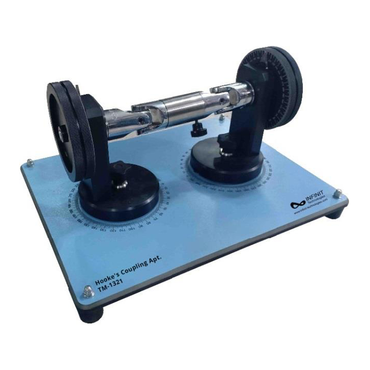
The table model demonstrates the transmission of angular motion to joint shafts, the related gimbal error and how this error can be rectified using Hooke’s couplings. The model consists of two Hooke’s couplings that are connected by a split intermediate shaft. The deflection angle of both joints can be set individually and read on the scales. Drive is achieved by turning a hand wheel. On the drive and power take-off sides there are further angle measuring scales made of transparent plastic with which the difference between the angles of the shafts can be determined.
Experiments
- Determination of the gimbal error on Hooke’s couplings.
Specifications
- Bench top experiment on gimbal error and its avoidance on articulated joints
- Hooke’s coupling, standard industrial parts
- Scales made of transparent plastic
- Ball bearing mounted shaft ends
- Solid, painted base plate
- Representation of universal joint


